
Hacking the Butternut HF2V
Matt Roberts - matt-at-kk5jy-dot-net
Published: 2019-05-08
Updated: 2023-02-18
Adding 30m and 20m to the HF2V
The Butternut HF2V
is a legal-limit HF vertical antenna for 80m and 40m. This is a nice
two-band vertical that uses a time-tested design. A single capacitor
and two inductors resonate the entire 32' device on both bands.
At one time, kits were offered for adding
30m and
160m
to the antenna. Each kit added an inductor, a capacitor, and some other
hardware to support each new band. Unfortunately, such kits have not been
available for quite some time.
I recently wanted a simple antenna to do some casual digimode DX work on the bands
most active during the solar minimum, namely 80m through 20m. So I decided to
find a way to add
30m and
20m
to the HF2V. The resulting four-band antenna gives me a single transmitting
antenna, capable of handling high power levels on the most active and popular HF
digimode bands.
And as it turns out, it was not difficult at all.
The Starting Place
The stock HF2V is a reasonably simple antenna. It has two inductors and a
single doorknob capacitor, placed a few feet up from the base. It acts as
a λ / 4 vertical on 40m, and a loaded
λ / 8 vertical on 80m. There is plenty of room,
both below and above the stock inductor assemblies, to add components to support
additional bands.
My strategy was to start with a stock antenna and a good radial system, then add 30m,
and test the results. Once that was done, I worked on 20m, which took a little
more experimentation.
Adding 30m
Upgrading the HF2V for 30m is well-documented. A number of people have written
web articles describing their hand-built 30m add-ons for their HF2Vs, some of which
are also hand-made.
 HF2V with 30m Coil
The main difference between the 30m assembly on the two models is where the
capacitor was oriented. On the HF2V, the 30m capacitor was placed beneath
the inductor, while on the HF6V, it is above. Since the 30m assembly is just
a series LC circuit, it doesn't matter which orientation is used. The HF2V
and HF6V also differ slightly on how the 30m assembly is connected to the 40m
circuit, but here also, either approach is fine. I chose to connect the
lower end of the 30m assembly to the midpoint between the 40m and 80m
coils, leaving the new 67pF capacitor on the top bracket.
The HF6V is a shorter antenna than the HF2V, so the inductance required for 30m
resonance is significantly less on the HF2V. As a result, I only needed
about 60% of the 30m coil for a comfortable resonance. The 30m coil was tapped
about 40% of the way up from the bottom, with the turns below that left floating.
Mechanically, the 30m coil was supported on a length of 3/4" ID PVC, which
holds the coil stretched to the optimum length required for resonance.
The 30m capacitor bracket holds the assembly in place from the top, leaving me to
fashion a hand-made stand-off to stabilize the bottom of the length of PVC.
The tune-up procedure was essentially identical to that described in the
30m kit manual.
The resonant point of this antenna on 30m provides about 100Ω at the antenna
feedpoint. The original 30m kit for the HF2V included a length of 75Ω
cable, which
functions
as an impedance transformer on 30m, to match the 100Ω feedpoint impedance
to 50Ω cable. Since the uncorrected impedance of the antenna on 30m
is only a ~2:1 mismatch (and even less at the radio), I chose not to add
the matching cable. Instead, the radio's built-in
ATU was more than enough
to trim out the minor mismatch.
For people wanting to use the 75Ω matching cable, DXE has a
premade cable available
for this purpose. It appears to be little more than a λ / 4 length
of (admittedly very nice) 75Ω cable, which should be around 15'4" long,
assuming a
VF of 66%, or 19'8",
assuming VF of 85%. I have not tried this, but I would be interested to hear
from anybody who does.
Adding 20m - Option #1
 HF2V with 20m Mast
Unlike the well-documented 30m addition to the antenna, I couldn't find any
internet articles describing a 20m modification for this antenna—not even
improvised ones.
Taking a cue from the 15m band arrangement on the HF6V, I discovered that the 20m
band could be added to the HF2V by attaching a second vertical element, in parallel
with the main 32' vertical mast, offset laterally by about 16". This is
essentially a "fan" arrangement, more commonly seen with multiband dipole
antennas.
The new element is is just shy of 15' in height, and connected to the main mast
at the 30m top bracket by a jumper of about 20". This gives an overall
20m element length close to λ / 4, which suggests that the
30m and 40m capacitors are electrically shortening the antenna on 20m by the few
extra feet between the 20m jumper and the ground. The new element added a
20m resonance with a ~1.4 match, measured at the antenna.
I used a stainless P-clamp to connect the jumper to the 20m element, allowing the
center of the 20m resonance to be adjusted simply by sliding the P-clamp up or down
on the element. The 20m antenna itself was made from several feet of
0.5" threaded aluminum tubing,
topped by a 6' mobile whip antenna.
Unfortunately, DXE has also chosen to discontinue their very nice mobile
masts. That said, any λ / 4 metallic or wire
vertical element should work. My first draft of the 20m add-on used an
MFJ stainless telescoping whip,
which was handy for making quick length changes to find the optimum height for
best match. The MFJ whip might be a viable long-term alternative, provided
that the joints between sections can be weather-proofed to prevent water
intrusion.
The vertical positioning of the 20m element does not appear to be particularly
critical. What does seem to matter is the total length of the element and
the jumper wire used to connect it to the main antenna. There is probably
a lot of flexibility in how one attaches such an element, including the spacing
from the main mast, etc.
Adding the 20m whip causes small changes (maybe 100kHz to 200kHz) in the
resonant points for the three other bands, with the larger change seen
on 80m. Adjusting for such changes isn't difficult, but expect to
re-tune the entire antenna when adding new bands using this option.
Adding 20m - Option #2
 Second 20m Design
After using the above 20m scheme for a few days, I came to dislike the mechanical
and electrical details. First, the high-mounted whip was a little unwieldy,
and none of the mounting schemes turned out to be satisfactory. Second,
the electrical interaction between the 20m element and the other bands seemed
undesirable. The 20m energy flowing unnecessarily through all of the
reactive components for the other bands isn't ideal for minimizing losses.
My second attempt at a 20m add-on solved all of these issues with a single
change. What I did was to mount
the 20m element lower on the main antenna, connecting it below the 80m
inductor. The jumper between the 20m element and the main antenna was
attached to the bottom clamp bolt of the 80m shorting bar.
The updated 20m element was easier to support, as I was able to secure more
of the length of the whip at various points along the lower 8' of the main
antenna. This stabilized the whip immensely, while having less wind
load above the top support. Fiberglass rod, like that used for inexpensive
electric fence posts, was used for stand-offs, to secure the two elements at a
constant distance from each other. Combined with the short piece of PVC
underneath the 20m element, this keeps the 20m element insulated from everything
else, except where the jumper connects it to the main antenna. P-clamps
were used to secure the standoffs to the elements at right-angle joints.
Since this arrangement is now essentially two antennas in parallel,
sharing the same radial fan on the ground, it also eliminated the 20m current
flowing through the reactive elements in the middle of the main antenna.
The Z value of the main antenna on 20m is very reactive, making it
essentially RF-invisible at 20m. This isn't really a 20m addition
to the HF2V anymore, as it is an independent element worked against the radials,
but it still allows me to use the single coaxial feedpoint and radial fan to
drive all four bands, which was my main goal for 20m.
Unlike with the other 20m strategy, there was essentially no interaction
between 20m and the other bands with this arrangement. This is despite
the 20m element being closer to the reactive elements than with the earlier
design. Once I had the antenna readjusted for the bottom three bands,
adding the 20m option lower on the antenna had no measurable effects on the
other bands' resonant points. So the interaction issue was greatly
improved with this updated design.
The updated 20m option does require about one foot more length on the 20m
element. I have lots of extra mast tubes of different lengths, so it
was no problem to add some length.
Here is a simple schematic showing the
antenna after installing second option.
Both 20m strategies work. It's just a matter of which one is
preferred for a given installation.
Adding the 20m element also greatly improved the overall antenna's imepedance
match on 17m and shorter bands. It would probably be worthwhile to model
the composite antenna to see what the pattern looks like on each of those
bands. A quality ATU is still needed to operate the antenna on those
bands, but I have received a number of good signal reports on 17m from stations
at rather low arrival angles.
Some time back, Ray (GM7NZI) sent me a
photograph of instructions
for a 20m kit offered by Butternut long before it was acquired by
DXE. That kit used two vertical wires in a
cage arrangement,
but is otherwise very similar to my second 20m option.
I haven't tried this arrangement, but thanks to Ray for finding
this document. It is definitely a third option for a 20m
homebrew kit for the antenna, complete with instructions from
the original Butternut company.
Measurements
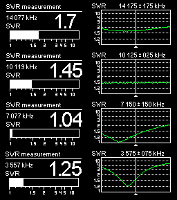 SWR Readings
The readings shown at right were taken by an antenna analyzer, with about 75' of
LMR-400 between the antenna and the device. Click on the image to enlarge it.
We have very good electrical ground quality here, and that certainly affects
the specific impedance values. As with all verticals, expect some variation
due to ground constants.
There is also a small shunt inductance (sometimes known as a "hairpin"
match) at the base of the HF2V. This inductance raises the feedpoint
impedance on 40m and 80m, so that the 36Ω (or less) natural impedance
of the antenna on those bands is raised closer to 50Ω. Since the
extended coverage from 80m to 20m is approximately two octaves, I adjusted the
shunt inductance for the best match on 40m, which is the "middle"
band. This should give the best balance between the outer bands.
A Note About Capacitors
The doorknob capacitors on the HF2V appear to be very high quality. Even with
the temperature variation from day to night in the summertime, there appears to be
very little Z0 drift over time.
That said, these capacitors are not inexpensive, and they are becoming increasingly
difficult to find, if one needs new ones to replace damaged parts.
In an effort to preserve the service life of the capacitors, I added a PVC shroud
to each of them, formed from a piece of thick (schedule 40) PVC pipe, split along
the length. The PVC forms an extra shell to protect the caps from solar
heating, and from other hazards such as hail. The pipe was chosen so that
the ID was somewhat larger than the capacitor bodies, to leave an air gap to
allow proper cooling through the ceramic.
Some care should be observed when doing this, since PVC is an imperfect insulator
at very high voltages. I made sure that the PVC can't touch both sides of the
circuit of either capacitor at once, and thus preventing current from trying to flow
through the PVC from one side of the cap to the other.
Maintenance and Reliability
The overall HF2V design is a time-tested one. The construction is generally
telescoped aluminum tubing, with electrical connections at mechanical joints being
made between two pieces of aluminum, or one piece of aluminum and one piece of
stainless steel. This provides good resistance against failures due to
corrosion of the mechanical joints caused by weather exposure.
However, telescoping aluminum verticals do have a weakness, and the HF2V's design
further exaggerates this failing. I noticed my HF2V struggling with with
intermittent connections after perhaps three or four years outdoors. The
problem is easily fixed, and can be avoided altogether with a little care applied
during assembly.
Mechanical joints made from telescoping aluminum tubing will eventually start showing
intermittent electrical continuity issues due to dirt and contaminants. Rainwater
wicks these contaminants into the joints between the tubing sections, where they collect
and eventually cause the joint to fail, electrically. The contamination can
corrode the electrical connection between the joints, but it can also simply make the
joint too dirty to make good contact.
The best antenna designs use stainless steel hose clamps to secure the larger tube
to the smaller one, applying roughly equal pressure to the entire circumference of
the tube cross-section, save for the slit used to allow compression. This tends
to resist the flow of dirty rainwater into the joint. The HF2V uses a somewhat
cheaper approach, of using a stainless machine screw with a double-slit tube, to
hold each section in place. This applies pressure at only two points on the
circumference of the tube, allowing much more of a gap to form between the tubes.
When I last disassembled the HF2V for cleaning, I made some changes to keep such
failures from recurring.
First, I wet-sanded the contact area for each tube, both inside and outside, then dried
the tubes. This removed corrosion and contamination that already existed. For
the outer surface, I used a mouse electric sander, but for the inside of the tubes, I had
to sand these by hand. The tubes aren't terribly thick-walled, so I wouldn't use
anything more aggressive to try to clean the joints.
Next, I replaced all of the machine screws between sections with stainless steel hose
clamps. Since each joint already had a slit top, there was no reason to use screws,
as a hose clamp provides more connection pressure over more of the joint, and closer to
the top of the lower tube, where contamination tends to start.
Last, when reassembling the tubes, I placed a generous coating of dielectric grease on
the end of each tube, before inserting it into the larger tube below it. This is
the same type of grease that is used to waterproof light sockets and spark plug wires
in your car, to prevent the electrical connections from corroding. When the tubes
are joined together, the insertion motion smears the grease down the length of the
contact area of the joint, and essentially waterproofs the joint. When the
hose clamp is tightened, the aluminum tubes are squeezed into electrical contact,
but the grease keeps rainwater running down the tubes from carrying contaminants into
the joint. Combined with the joint pressure from the hose clamps, this should
result in a near-permanent installation that is free from contamination and failure.
What about 160m?
The HF2V once had a standard kit for adding 160m to the antenna. Very similar to
the 30m kit, the 160m add-on included an inductor and capacitor. The inductor
adds enough reactance to resonate the entire length of the antenna on 160m, while
the capacitor bypasses the inductor for 80m and shorter wavelengths.
The 32' mast is very short for 160m operation, so the reactance values required are
quite large, and the usable bandwidth is very narrow, as one might expect.
The
original instructions
indicated that 10kHz is a reasonable 2:1 VSWR bandwidth for the HF2V on 160m.
This can be broadened by
top-loading the antenna.
The narrow bandwidth is fine for "watering hole" modes like the newer
soundcard digital modes. With the aid of a wide-range ATU on one's
transmitter, the antenna can cover the vast majority of the CW segments commonly
used for 160m contesting. That's good enough for me, so despite the
limitations, I built and tested a simplified 160m add-on for my HF2V.
The capacitors of the Butternut verticals allow the antenna to present resonances
on multiple bands at once, and the large capacitor from the 160m kit is no different.
The original 160m bypass cap is 400pF, assembled from two each, 200pF 15kV ceramic
"doorknob" caps in parallel. While the 160m kit is no longer offered by
DXE, they do still sell the 200pF caps. Note that you will need at least two of
them, and they are not cheap. Mouser sells 200pF and 400pF Vishay doorknob caps
with 50kV rating for about $44 ... these might be good substitutes, but I have not
tried them.
Since I use 160m only occasionally, I chose to forego the capacitors that allow seamless
160m band switching, and opted for an approach that adds only an inductor. In
simple terms, when I want to use 160m, I transmit through the inductor. When
I want to use other bands, I short out the 160m coil completely.
Skipping the capacitive band switching has some nice side effects. First, the
other bands of the antenna do not have to be adjusted to cancel out all of the extra
capacitive reactance from the 160m cap. This also means that the 160m kit can
be attached or removed completely without affecting the other band adjustments.
Since the 160m cap causes a narrowing of usable bandwidth on 80m and 40m, omitting
it preserves the bandwidth of the higher bands. The only trade-off is switching
the 160m inductor by other means.
The factory kit included a very nice inductor made from heavy aluminum wire.
Like the other stock inductors, the ends were insulated from each other by a length
of fiberglass rod, which also allowed the inductor to be stretched to adjust its
value. For the hand-made version, I chose to wrap #12 THHN stranded copper wire
on a 2.375" OD PVC pipe. Since the 30m add-on changes the magnitude and physical
location of the reactance on the antenna, the required size of the 160m inductor is
different depending on whether the 30m kit is installed. For a target center
frequency of 1835kHz, the inductor required 53 turns on the PVC form without the
30m kit. With the 30m kit installed, the inductor required closer to 61 turns
on the same form.
If the antenna is top-loaded, the inductor size will need to be reduced
accordingly. If a 400pF capacitor is used to allow simultaneous resonance of 160m
with the other bands, similar to the original Butternut kit, the required inductance
will likely be a bit higher.
I used an alligator clip to short out the 160m inductor when not in use. It would
not be difficult to add a waterproof SPST switch or relay to make the task of disabling
the 160m coil even easier. I also sprayed a couple of layers of clear enamel paint
over the coil assembly to protect the nylon coating of the THHN wire from UV damage.
Adding 160m to the HF2V adds another octave to its range. This makes adjusting
the shunt inductor at the base of the antenna more of a compromise between the bands
installed on the antenna. Even with the 160m kit installed, I prefer to adjust
the shunt inductor for best 50Ω match on the 40m band. This raises the
measured SWR on 160 to over 2:1, but I'm happy to use an ATU to trim that out at the
transmitter. The reflection-induced coaxial cable losses on 160m are tiny,
even with a 2:1 or 3:1 mismatch, so I prefer to match the higher bands where losses
add up more quickly.
160m can be quite active during the winter months. During a recent Sunday evening,
my 100W signal was heard coast-to-coast by numerous stations as shown at right.
Copyright (C) 2019-2021 by Matt Roberts, KK5JY.
All Rights Reserved.


