
Hacking the J-Pole Antenna
Matt Roberts - matt-at-kk5jy-dot-net
Published: 2022-05-25
Updated: 2023-03-15
Making a Smaller J-Pole
One of the more popular designs for home-made transmitting antennas is the
J-Pole. The J-pole is a
single-band, feedline-matched, vertical antenna that is easy to construct, and offers
a reasonable amount of gain near the horizon, making it a favorite with hobbyists for
VHF and UHF terrestrial FM communications.
Electrically, the J-pole belongs to the family of so-called
end-fed dipole antennas, very similar to the
W1BX Ringo
series of products. The advantage of these antennas is that they are vertical dipoles,
fed at or near the bottom of the radiating section, eliminating the need for radials,
center insulators, etc. This allows the antenna to be built, installed, and
supported easily in places where a more traditional center-fed dipole or
GP antenna
would be impractical.
At and above the high
VHF range,
a J-pole antenna is a reasonable size, and generally easy to support, but as the frequency
falls, the overall 0.75λ height of the J-pole can become large enough so as to
require substantial mechanical support. This makes them impractical for
residential HF use.
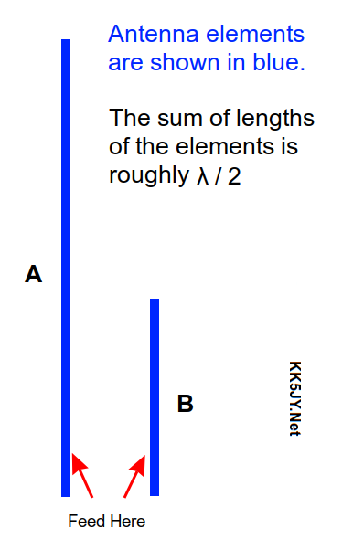
Figure 1: Diagram
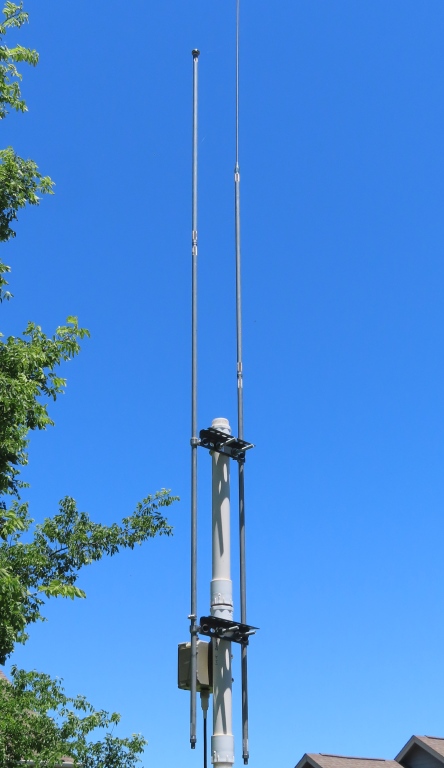
Figure 2: Prototype
for 10m
Forutnately, it is possible to build a vertical dipole, fed at the base of the antenna,
but in roughly half the overall height of a J-pole antenna—even shorter than a
comparable Ringo. To accomplish this, we simply rearrange the dipole and its
feedpoint a bit:
- Start with a λ / 2 vertical conductor.
- Break the conductor between the center and the lower end.
- Fold the smaller piece upward, parallel with the larger piece.
- Attach the coaxial feedline across the break in the conductor.
This essentially creates an off-center-fed (OCF) dipole antenna, with the smaller
bit folded back over the larger bit. Feeding the dipole off-center raises the
impedance significantly, but folding back part of the antenna causes the impedance
to fall, as compared to a conventional center-fed dipole. The trick is to pick
a point to break the dipole so that the impedance changes cancel, leaving a feedpoint
impedance close to 50Ω.
For now, I'll call it the SJ-Pole. Maybe somebody can suggest a
better name for it later.
The Prototype
A prototype for this design has been built for
the 10m band. The details
are quite simple:
- Support two vertical metal masts, separated by about 6".
- Attach the coaxial cable at a point between the masts.
The mechanical design uses clamps to support the masts and the cable connections,
to allow moving the feed point and the relative vertical positions of the masts
after assembly. This greatly simplifies the adjustment of the antnena for
resonance.
The prototype uses aluminum mast
segments for the elements, with the longer element topped by a
stainless steel whip.
There are a number of other materials that could be substituted for the elements, including
hard-drawn copper pipe, small-bore electrical conduit, etc. The masts were secured to
angle-iron cross-members using P-clamps, with PVC insulators between the elements and the
clamps. The insulators were cut from hot-water CPVC pipe.
Once the antenna is raised into position, the feed point is moved vertically on
the masts, to find the best match. If the antenna does not match the cable at
resonance, adjustment of the resonant impedance can be done by moving each mast
vertically, to lengthen or shorten the height of a single mast above the feed point.
By varying the overall length of the antenna elements, and the position of the feed
point along that length, a 50Ω match can be reached.
A basic diagram of the electrical antenna is shown at right. For the 10m
prototype, resonated around 28.3MHz, the adjusted lengths above the feedpoint
for 50Ω match was found to be A = 152", and B = 62",
with a 6" spacing between the elements. This is a few inches longer than
the theoretical length for a resonant dipole. I suspect the difference is due
to stray capacitance between the elements and/or the steel in the supports.
Both the EZNEC+ model and the prototype antenna indicate that the lengths required to
match a 50Ω cable are for the smaller element to be ~29% of the sum of the element
lengths. This is probably a good starting place for modeling the antenna for other
bands.
As with most vertical antennas, the pattern is omnidirectional. Over good ground,
it offers a peak gain of ~1dBi at an elevation angle between 12° and 19°, depending
on the installation height. For best performance, the base of the antenna should not
be installed more than λ / 4 above the ground.
Other Considerations
As with all OCF dipole designs fed with coaxial cable, the cable should be
choked appropriately.
I used two different commercial products during testing, the first was a Balun Designs
model #1110,
then later a
model #1113.
The latter is a higher-power and weatherproof version of the former. For antennas
built for VHF, 10m, or the upper HF bands, several turns of coaxial cable on a nonconductive
mount would likely work just as well.
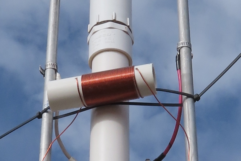
Figure 3: Static Drain
One feature of the original J-Pole is that it uses a shunt inductance
at the feedpoint, which matches the antenna to 50Ω. This
also forms a short-circuit at DC and provices excellent static and
lightning protection for the antenna when properly grounded.
Unfortunately, the SJ-pole lacks this feature.
To correct this, I added an inductor beteween the elements, to serve as
a static drain. It was made from ~50 turns of magnet wire on a
1" ID (25mm) PVC form. This provides a lot of inductance,
which keeps it from interfering with the impedance of the antenna.
The inductor is a short-circuit at DC, providing the desired static
protection.
Multiband Operation
As with other dipole antennas, there are at least a couple of different
ways to use the SJ-pole successfully off-band. One is to match
the antenna at the mount; the other is to use the ATU
built into many transmitters and amplifiers.
Replacing the choke with an
SG-230
mounted to the side of the antenna, the antenna readily matched
all HF bands from 10m to 160m. Even when using the coupler
in a matched condition it's still important to choke the coaxial
feedline and power cable. I looped the 230's cable through
a large #43 bead to accomplish both together.
On the higher HF bands, this arrangement worked flawlessly, making
numerous contacts with excellent average signal reports. On
the 20m and 30m bands, the signal reports were more break-even, but
the antenna still had no problem being heard. On 40m, the
short antenna was starting to struggle, so as with most dipoles,
the rule of thumb applies here, too — the antenna should
be sized so that it is no smaller than λ / 4 overall
length, for best performance.
On the higher bands, the SG-230 wasn't necessary, and the bare
antenna matched fine with the radio's ATU. This arrangement
also showed good contact reports between 10m and 17m. On
20m and longer bands, the mismatch was just too high for my
radio's ATU, which is limited to about 10:1 mismatch.
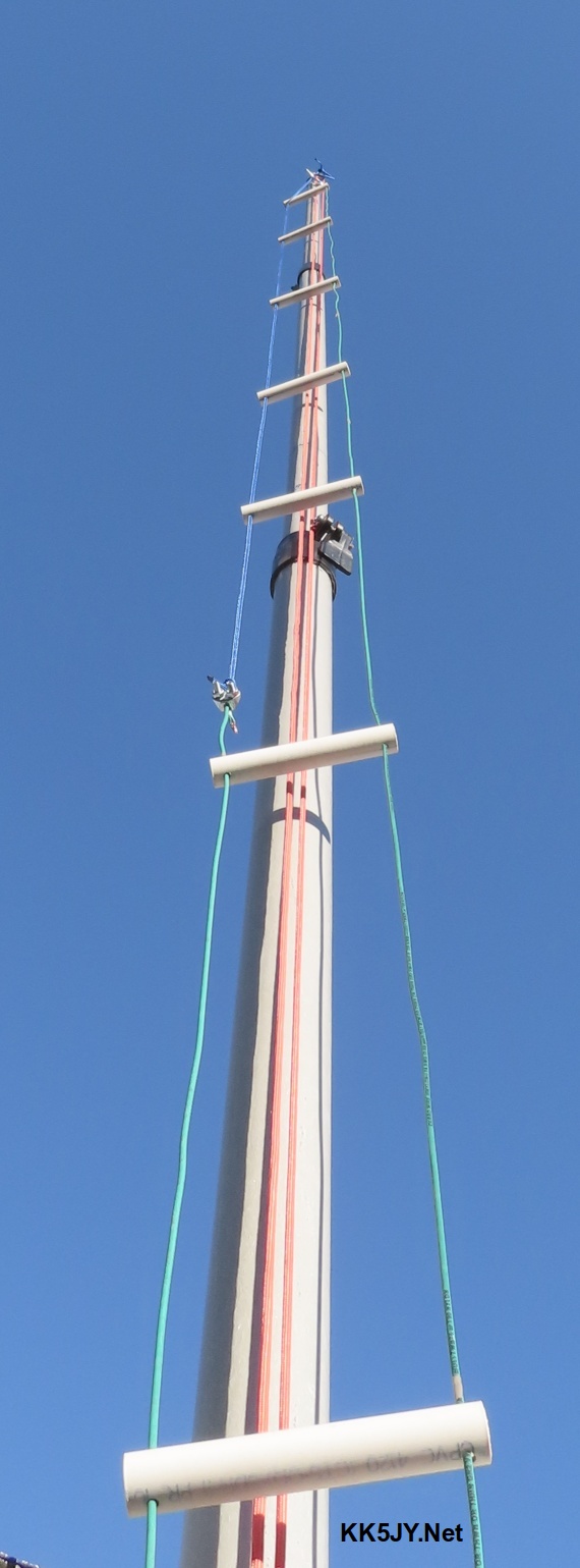
Figure 4: Ladder
Line Construction
It's good to remember that my prototype is sized for 10m, so even
with the remote SGC tuner at the antenna, making contacts at three
times that wavelength is farily impressive. A slightly
larger antenna with the same proporions should make a solid
upper-HF antenna for 20m through 10m, especially with a remote
ATU.
It's also possible to cover a couple of bands without an ATU at
all if you tune the antenna in between bands. I found that
if I added one foot of length to the longer leg of the 10m
version of this antenna, I could cover both 10m and 12m well,
with mismatch under 2:1 at the radio.
Alternate Construction
The SJ-pole can be easily built from wire if you have appropriate
supports for it. I recently built a 15m version out of spare
hand-built ladder line. I cut the ladder wires so that the
conductors were the appropriate length, then replaced the missing
wire with rope, to preserve the ladder mechnaically along its
length. The result is shown at right.
The ladder uses a 3.5" spacing, but otherwise the same geometry
as the 10m prototype. It tuned right up and even with 90W, it
had no problem being heard
around the world.
So spacing isn't particularly critical, as long as
the feedpoint is chosen near the 50-Ω point between the
conductors.
Even as a single-band antenna, this project provides a lot
of antenna in a small space. I am normally skeptical
of "no-radial antennas" but this one convinced me
that it can be done.
—
Copyright (C) 2022-2023 by Matt Roberts, KK5JY.
All Rights Reserved.