
A Small Transmitting Loop for 160m
Matt Roberts - matt-at-kk5jy-dot-net
Published: 2016-12-07
Updated: 2017-01-29
With the sunspot cycle on a quick descent going into 2017, it is time to think about
getting serious about antenna systems for the longer wavelengths. I recently gave
myself the challenge of making a serious attempt at 160m contesting. The main
challenges when working 160m are designing effective antennas. I already have an
effective receive antenna for the low bands, in the loop-on ground,
developed over the summer months. That antenna has given me excellent results when
listening to the bands between 160m and 20m. So the last remaining piece of the 160m
puzzle is an effective transmit antenna.
The internet is awash with articles on different 160m antenna designs, each with its own
set of design compromies and trade-offs. These range from the loaded verticals, such
as the inverted-L, to the various loop antennas, both vertical and horizontal, and everywhere
in between. Loaded dipoles for 160m can be made to fit into the space of a 40m dipole,
but unless a very tall tower is available, they tend to be effective only for high-angle
(NVIS) contacts. Since 160m can carry both high- and low-angle contacts during the
evening hours, I was hoping for an antenna that could exploit both, in the same way that
the loop-on-ground antenna can hear both high- and low-angle contacts simultaneously.
The Concept
For other bands, I have built transmitting loops that exhibit
this property for both transmit and receive, and so I set out to investigate whether
that could also be done for 160m. Although a compact transmitting loop
for 160m would be difficult to construct in such a way that it would also be efficient,
a small transmitting loop for 160m turns out to be fairly straightforward.
What is the difference between a compact loop and a small one? A
compact loop is what we are used to seeing with the typical HF "magloop" --
something that a single person can carry out into the yard and stand up by himself.
Such loops tend to range from 1' to 6' in diameter, and are "man portable."
They also happen to be electrically small, in that their circumference is very
short compared to the wavelength of operation, on the order of 5% to 30% of the
transmitted wavelength. Most texts on the subject treat any loop antenna with a
total circumference of less than λ/3 as an electrically small antenna. As
it turns out, building a 160m loop antenna with a total circumference of λ/3,
even within the restricted space of a residential yard, is not difficult at all.
However, I also wanted my antenna and feedline to be as efficient as possible, and for
them to be able to handle high power levels. Efficiency requires that the feedline
run with minimal SWR, which means that the antenna needs to be matched to the feedline
at the connection to the antenna. Remote autotuners can do the trick, but they tend
to be very power-limited. My goal was to be able to run 700W CW into the antenna
system, which meant no autotuners. As it turns out, the small 160m loop can be
tuned with a single high-voltage capacitor, just as with the other small transmitting
loops. This allows tuned QRO operation without a remote tuner. And since
there is only one variable-reactance element in the tuning circuit, the antenna can use
automatic loop tuner software to keep the antenna resonant
as I chase up and down the band during a contest.
The yard behind my house has one 30' tall mast near the center, which can serve as the
center support of a delta loop. To this, I added a couple of 11' fiberglass
supports at the corners of the yard to support the base corners of the loop. As
it turns out, this arrangement gave me just enough working room to fit a wire loop with
circumference of λ/3 into my yard, with plenty of buffer between the antenna and
the closeset neighbors. Both transmit and receieve antennas were oriented so that
their main lobes pointed roughly ENE and WSW. This directs the main lobes in the
direction of the majority of US and worldwide hams. The RF safety calculator
showed that such an antenna could safely run 700W CW on 160m, keeping the minimum safe
distance (for both controlled and uncontrolled environments) completely within my own
property. So the delta loop made the cut for the 2016
ARRL 160m Contest.
The Model
This antenna is, by definition, a small transmitting loop, despite its nearly 30m
wingspan. The EZ-NEC+ model, elevation plot, and SWR sweep are shown in
Figure 1.
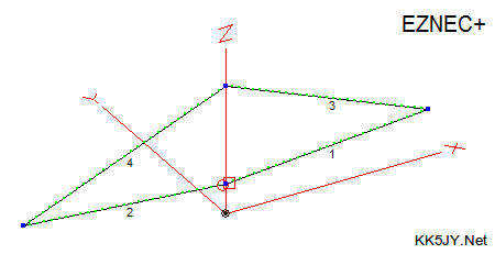
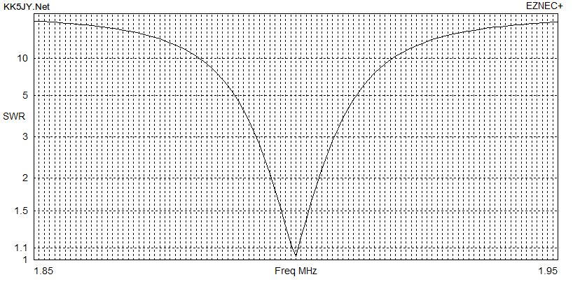
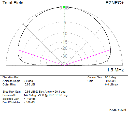
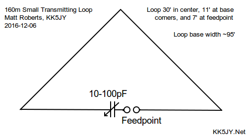
Figure 1: EZ-NEC+ Model and Data
The elevation plot is in the plane of the wire loop, with the maximum signal produced
bidirectionally off the ends. As can be seen from the plot, this antenna has
excellent high-angle response, but it also has far better low-angle response than a
low dipole. The -3dB elevation angle is less than 20°, while the -6dB
elevation angle is around 6°, giving the loop a much better DX capability than
a low dipole, and competitive with loaded verticals.
The SWR plot shown is between 1.85 and 1.95, or the middle 50% of the band. To
fully resonate the antenna, some capacitance was added to the model, shunted across the
feedline. In practice, this extra capacitor was not needed, likely due to stray
capacitance at the feedpoint provided by the choke and/or the metal mast. One
challenge of 160m is that the reactive near field radius is dozens of meters around
the antenna. So stray interactions can be unpredictable.
The Prototype
The loop used for the December contest was made with #14 stranded wire. Using
#12 wire would have provided around 1dB of signal improvement, at the cost of doubling
the weight of the wire. One advantage of the 160m band is that the skin effect
causes far less loss than on other bands. As a result, all conductors in the
antenna circuit and feedline can be thinner or smaller than would be effective on
higher bands.
The loop is fed in the center of the base wire. The tuning capacitor is placed
in series with one half of the base wire, on one side of the feedpoint. This
results in an antenna that is resonant and balanced, but not DC-shorted. As a
result, care should be taken to provide proper grounding and static/lightning protection
for the feedline when it enters the building. The resonant point shown was
obtained by using ~35pF of capacitance.
The feedpoint and tuning section of the antenna is shown in Figure 2, both
with and without the gearmotor I used to remote-tune the antenna while operating,
as well as two pictures of the installed unit, both with and without the protective
"birdhouse" I used to keep weekend weather away from the capacitor.
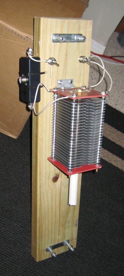
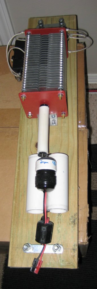
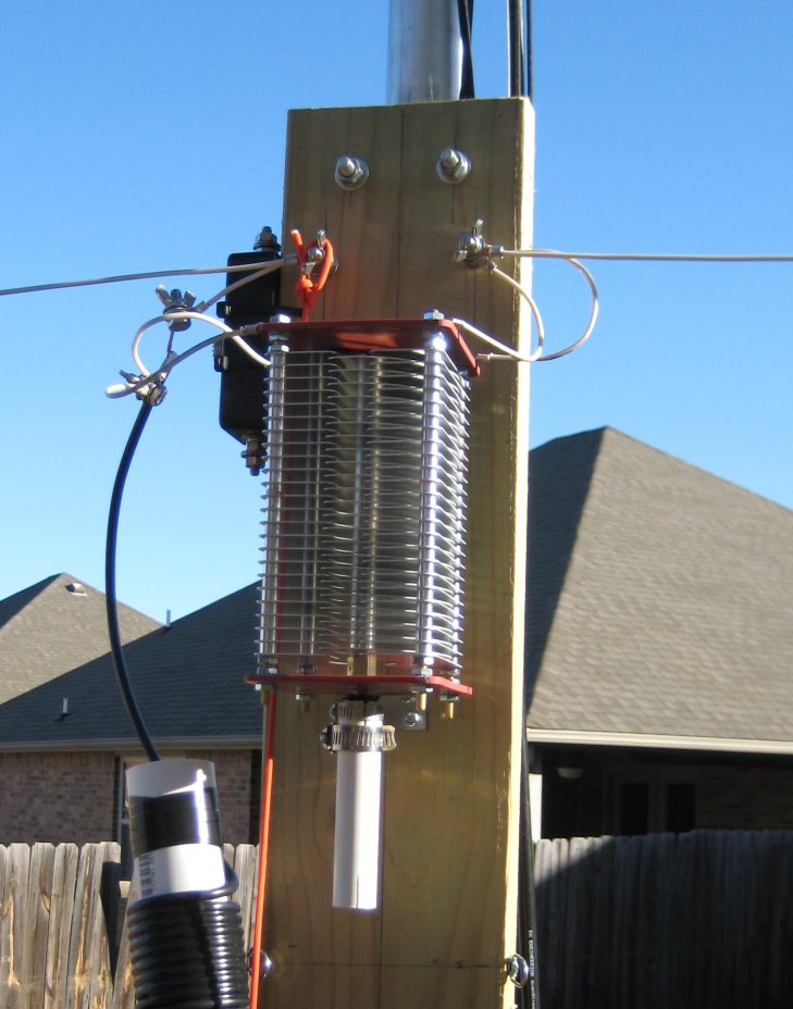
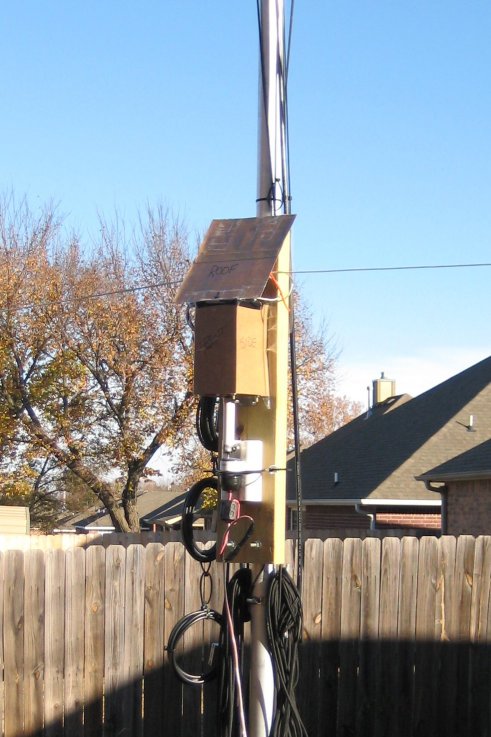
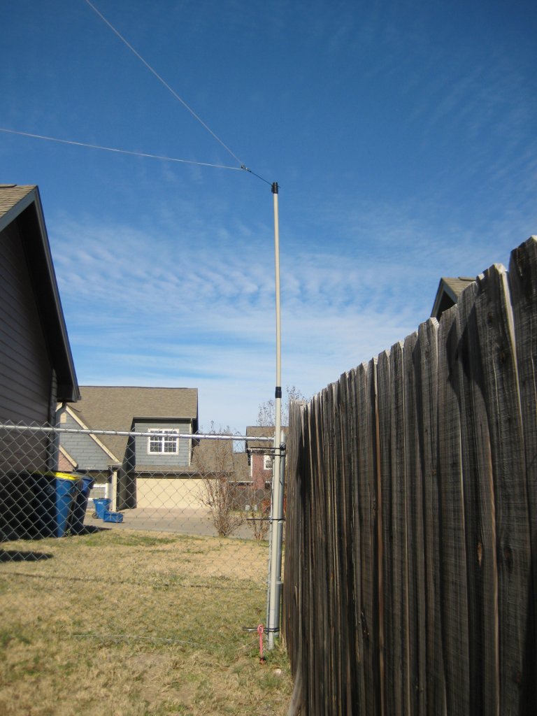
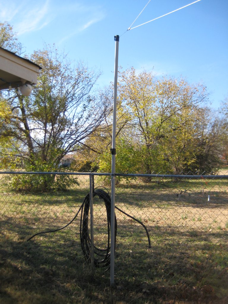
Figure 2: Feedpoint, Tuning Capacitor and Motor, and Corner Supports
The motor was omitted during early test standing. Before the contest, the motor was
added to allow me to adjust the resonant point of the antenna remotely. The capacitor
used, a Palstar AT2KD, was used in
split-stator mode, with connections being made to the two stator halves, and the rotor
plates floating. This doubles the voltage capacity, and halves the maximum available
capacitance, by forming what is essentially two capacitors in series, using the rotor plates
as common between the two capacitors. The tuning of an air-variable capacitor is very
sharp, because there is no internal reduction drive, as is found in vacuum variables, so
the motor chosen has a gearhead that slows the full-voltage shaft speed to 2.0 RPM.
In addition, I used an Arduino running the AutoCap firmware
and a motor shield as a PWM controller to slow the motor speed even more when tuning.
The Choke Problem
As it turns out, the power handling capacity of this type of loop has two limiting
factors. The first is the voltage and current ratings of the capacitor.
These are straightforward to determine via modeling, as the model can be run with
whatever power level is desired, and the calculations will show the voltage and current
that would be developed at the capacitor, and those numbers can be used to select
(or construct) an appropriate part. I ran a model of my prototype loop, and
determined that the 700W power goal would require a capacitor capable of approximately
11kV at 5.3A. Simple enough. Less straightforward, however, is the selection or
construction of the other limiting factor, which is a common-mode choke to be used at
the feedpoint.
A base-fed delta loop is a balanced antenna, just like a dipole. Feeding even a
full-wavelength resonant wire loop requires a feedpoint choke, sometimes referred to as a
balun. Feeding a capacitor-loaded
small loop makes the choke performance critical, especially when QRO. As can be seen
from the pictures, several different chokes were tried. In fact, providing an
appropriate choke for this antenna turned out to be the largest challenge of the entire project,
consuming the majority of the development and installation time. This small loop antenna,
just like other so-called "magloops," consists of a capacitor and inductor in a tuned
circuit, with a similar pattern and current distribution. However, this antenna was
direct-driven from coaxial cable, rather than inductively or through a gamma match, as is
typical with compact transmitting loop designs. As a result, choking the feedpoint
becomes critical, to keep the feedline shield from detuning the antenna, or radiating energy
and distorting the pattern. As it turns out, this antenna required almost 20kΩ
of choke impedance to effectively decouple the outer skin of the feedline from the antenna.
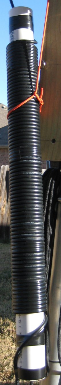
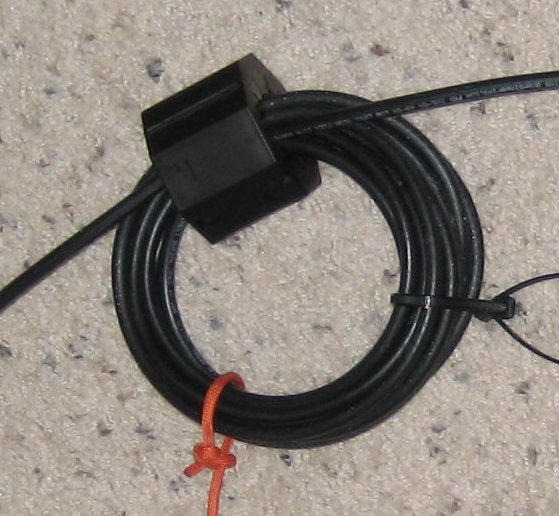
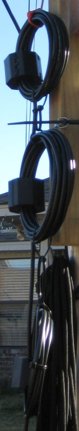
Figure 3: Early Choke Designs
I first tried a number of commercial chokes, including the
FCC050-H05 from DX Engineering,
and the
Model 1115 from
Balun Designs. Both of these devices are very effective on HF bands, but they proved
woefully inadequate as a balun for a loaded 160m antenna. I noticed that Balun Designs
now has a
Model 1116,
that is meant to provide extra XL at 160m, but even this device provides only
5kΩ of choke impedance.
This is probably fine for a loaded vertical, but when I did the calculations, it was obvious
that even the 1116 wasn't enough for this loop design.
As an aside, many coaxial feedline choke designs are somewhat compromised in their
construction. While they do provide sufficient XL to break the circuit
formed by the outer shield skin, many of these chokes are built into enclosures,
and connect to the outside world using flange connectors. The problem with flange
connectors is that they break the shield's gaussian surface completely, because the coaxial
cable inside the choke (the cable the wraps around the toroidal or binocular cores)
is cut, stripped, and attached to the flange connector as a pair of wires. This provides
a location for signal ingress and egress from the inside surface of the shield, partially
recreating the problem that the choke is supposed to fix. A far better design for
coaxial feedline chokes would be to use barrel connectors on each end of the choke, then
internal to the choke, use fully shielded connectors on the coaxial coil, to connect to the
barrels, thus maintaining the integrity of the coaxial shield all the way through the choke
enclosure. Even better would be to use crimp-on flange connectors that are essentially
the same thing in a single part. But I digress...
Several internet articles described 160m chokes built from coaxial cable coiled on a
piece of PVC. I built such a choke, but it fell far short of even the impedance
offered by the commercial products. I found out later that the cross-sectional area
of the PVC pipe is critical to the choke value, but after doing the math, even a larger
pipe gauge would not have provided the needed value.
I then used a choke made with eleven turns of RG-8X (the most that would fit) around a large
Material 31 core, which
provided far more impedance than either (or both) of the commercial chokes I had
available. Nonetheless, when I connected to the antenna, it also proved to be
insufficient for the task. If I stood clear of the antenna, the cable, the analyzer,
and kept all of these components away from metal and the ground, the antenna would
resonate. But if I reached over to touch the analyzer to move the frequency, just
the proximity of my hand would detune the antenna substantially.
Next, I tried three cores, each filled with turns of RG-8X, essentially forming
three chokes in series. This choke turned out to be mostly effective, and enough
so to work the contest. What I found, however, is that the choking effect was
very uneven between the three cores. When running, with power levels around 600W,
and duty cycle approaching 50%, the top core (closest to the antenna) would get warm,
the middle core would get quite hot (on the order of 50°C), and the bottom core would
stay cool. I am not sure why this happened, but the unequal heating of the cores
suggests that distributing the inductance is not a good idea, since ferrite longevity
is badly compromised by heat and/or mechanical stresses.
More importantly, heating choke cores is just bad for business -- any power from the
transmitter that is heating up the ferrite material is not being radiated into
space. So the choke design was actually hurting one of my design constraints of
having an efficient antenna. So a new design is needed for this antenna.
Several early choke designs are shown in Figure 3.
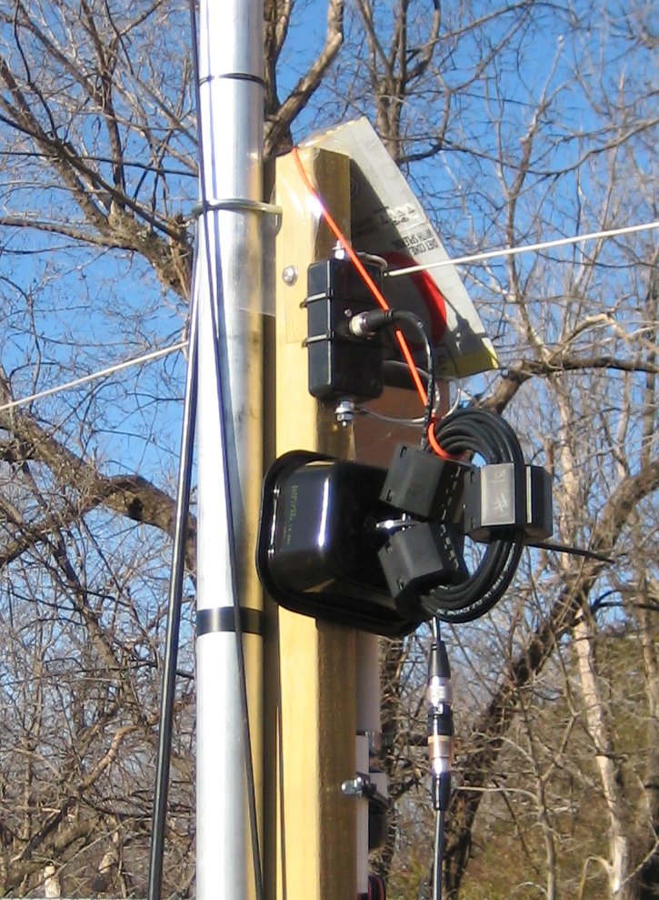
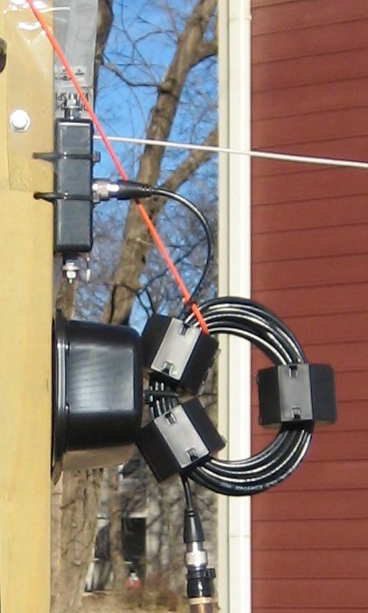
Figure 4: Single-Inductor Choke
Since cable losses are small at 160m, even for modest coaxial cables, it occurred to
me that I could get more core turns if I used a smaller cable. Breaking out the
calculator again, I determined that the orignal three-core series choke had around
17.5kΩ of shield impedance. As it turns out, moving to RG-58 allowed me
to put enough turns on a single core to get the same impedance. So I wound such
a choke in a single coil, with three 31-material cores. This choke does a much
better job of blocking common-mode feedline current, and using all three
#31 split
beads serves to increase the effective permiability of the inductor core,
improving the choking performance substantially. The resulting device consumed
25' of RG-58, with 17 turns of coax. Such a short run of RG-58 has
negligible insertion loss on 160m, and it saved me from having to use one of the
more expensive teflon cable designs.
Interestingly, the voltage handling capacity of the coaxial cable used on the choke
is not critical, since this antenna uses a capacitor to resonate the antenna itself,
providing a near-50Ω match during operation. As a result, even at maximum
legal power, the coax need only endure about 275V differential potential for a 1:1 match,
and less than 400V for a 2:1 mismatch. Any quality cable can endure such voltages
at 160m with ease, as even RG-58 has a dielectric rating of nearly 2kV. So as long
as the cable and cores stay cool, power handling should not be an issue for even the
largest street-legal amplifier.
This new design is shown in Figure 4.
Once this new choke design was added to the antenna, it was quickly apparent just how
much power was "leaking" out through the original choke. The original
antenna ran just fine at 700W, albeit with some substantial core heating, as described
above. When the new choke was tested, I could only take the power level to about
350W before arcing began in the capacitor. What this suggests is that so much
power was being absorbed in the old choke that the voltage at the tuning capacitor was
dropped enough to operate properly without arcing. That's 3dB of power loss!
The Palstar capacitor is rated at 5kV, and even if that applies from the rotor to each
stator stack, the 11kV provided at 700W may be pushing the series pair of capacitors
beyond their rating.
There are a couple of ways to increase the power rating of the antenna. First,
the capacitor could be replaced with a vacuum variable with a higher voltage rating, or
an air variable with wider plate spacing. Another option is to place a 100pF
fixed capacitor in series with the other leg of the loop feed. This capacitor
could be of similar rating to the AT2KD, because the new capacitor would be in series
with the AT2KD, lowering the voltage across each. And since the capacitors would
be in series, the resonant point would be reached when the AT2KD was adjusted closer
to 70pF, giving a relatively equalized voltage distribution. 100pF doorknob
capacitors are readily available and would be less expensive than a vacuum variable
replacement capacitor.
All things considered, however, running 300W from the amplifier, and having it all go
to the antenna, is still better than running 700W from the amplifier and seeing over
half of it dumped as heat into the choke.
More to Come
Despite the challenges posed by the balun, the overall antenna design was sound.
During the ARRL contest, from my Oklahoma location, stations were worked all over the US,
Canada and Mexico, plus several Caribbean stations, at all distances. This
antenna turned out to be an excellent complimentary transmit antenna to the
LoG, which was used as a low-noise receiving antenna. Having
a matched pair of antennas for transmit and receive is critical to reliable communications
on longer wavelengths, and the "talk" and "listen" performance of
these antennas was similar. On the one hand, I could work 99% of stations I could
hear, and when running (calling CQ), I didn't hear any stations that were too weak to
copy (nor did I see any such stations in the second receiver's panadapter).
Even when running with just 300W into the updated choke, I was also able to enter the
January 2017 CQ 160m CW contest, and the improved antenna design worked every bit as
well in it did when I ran 700W in the ARRL event. So the improvements were
definitely worth the effort. Between now and the December 2017 ARRL contest,
I hope to make some upgrades to the feedpoint so that I can work that event with full
amplifier power.
Copyright (C) 2016,2017 by Matt Roberts, All Rights Reserved.