The 6m Halo Antenna
Matt Roberts - matt-at-kk5jy-dot-net
Published: 2020-06-09
Updated: 2020-06-10
The 6m band is one of those
odd places in the radio spectrum that is like no other. I remember some 6m FM
contacts back in my college days that were crystal clear, car-to-car, using 4' whip
antennas, at over 1,000 miles distant. Openings like that didn't happen often,
but when they did, the performance was impressive.
While I mostly concentrate on HF operation, which has more predictable performance
over long distances than VHF, I recently did some tinkering on the 6m band. The
first order of business was to get an antenna in the air that didn't break the bank,
and didn't consume too much of the yard.
One of the more popular antennas for beginning VHF operators is the
halo antenna.
These come in various flavors, but the basic idea is that one starts with a
λ / 2 wire dipole, which is then bent into a circular or square shape,
which looks like a loop (but really isn't). Recently, this design has been
popularized by the
cobweb antenna, which is
several halo antennas for different bands, nested inside each other.
The halo has been long used on the 6m and 2m VHF bands for SSB, especially for mobile or portable
antennas, because they are reasonably small and easy to transport. The
commercial versions can be rather pricey, so I decided to build one myself,
using very simple techniques for mechanical and electrical considerations.
As it turns out, building a halo antenna is simplicity itself, and it can easily
match 50Ω cable. The antenna described below is for 6m, but the design
can be scaled for any band, including VHF, UHF, or even the higher HF bands.
The Model
The antenna is nothing more than a square loop of wire, approximately 30"
(or ~76cm) per side. The loop is fed in the middle of one side, and the
opposite side to the feed point has a gap in it. The result is a dipole
antenna bent into the shape of a square, with one side of the square being
slightly longer than λ / 8.
The antenna I installed was mounted on a piece of 10' fence rail that was extended
by a couple of feet by a piece of PVC at the bottom, giving an overall height of
~12'. This provides a single low-angle lobe that extends around the compass
to all azimuth angles.
An EZ-NEC+ model for the 6m halo is shown
below:
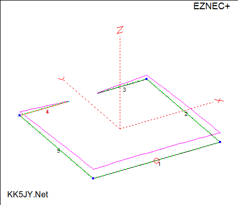
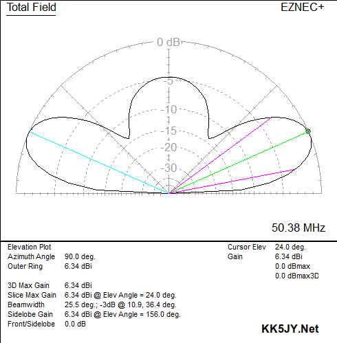
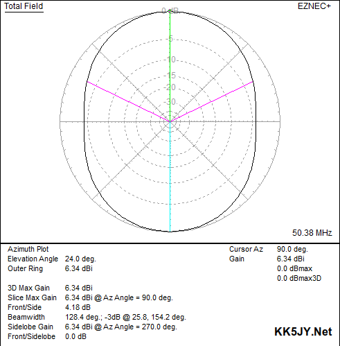
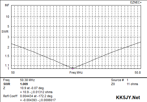
Figure 1: EZ-NEC+ Model and Data
6m Halo at 12'
As you can see, the azimuth pattern is nearly omnidirecitonal. This is one of
the few omnidirectional antennas that is also horizontally polarized. This allows
communications with other stations using horizontal polarization, but without needing a
rotor to point the antenna at the other station.
The peak gain over good ground is very respectable for such a small antenna, at over
6dBi.
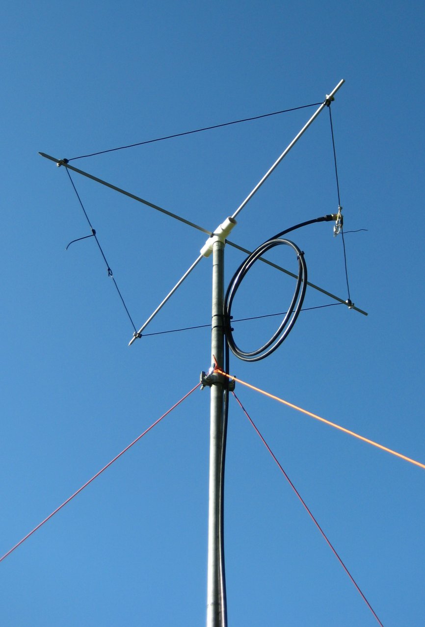
The Physical Antenna
Mechanically, the antenna was made from common components. The primary frame
is two pieces of 3/8" fiberglass rod, each 48" long, as commonly used for
electric fences. The rods are held in a "cross" or "plus"
shape by a 1" PVC "T", extended a few inches at each end with 1"
PVC pipe. The upper rod is zip-tied to the inside-top of the pipe, while the
lower rod is drilled sideways through the "T". Insulated P-clamps
hold the wire in place, and the P-clamps are held to the rod with small hose clamps.
The 1" PVC was chosen because the "T" will fit snugly over the top of
a 1" by 10.5' piece of galvanized chain link fence top rail. This allows a
single piece of rail to lift the antenna to over 10', which is where the pattern
really has its best shape.
The Electrical Antenna
The antenna is directly driven by coaxial cable. The resonant impedance of a
dipole bent into a square is on the order of 10Ω—a 5:1 mismatch to
50Ω cable. Matching to 50Ω cable is done by use of a small
feedpoint shunt inductor, sometimes known as a "hairpin." This is a
single turn of wire, connected in parallel with the antenna and coax. The
length of the single turn of wire is roughly a few inches, with the specific length
dependent on the height of the antenna above ground. The "hairpin"
provides a near-lossless impedance step-up, with the value of inductance adjusted
to raise the impedance to whatever value is needed. This allows the impedance
to be raised without changing the resonant frequency of the antenna.
 Figure 2: SWR Sweep
With the hairpin match adjusted, the feedpoint presents a perfect match to coaxial
cable. Either 50Ω or 75Ω cable can be easily matched in this manner.
The resonant frequency of the antenna is adjusted by changing the length of the wire
ends on the side opposite the feed point. If the wire length is initially a
little long, these ends can be trimmed to raise the center frequency of the antenna
to whatever value is desired. I started with ~55" of wire on either side
of the coaxial connector, and trimmed from there.
The SWR sweep of the antenna is shown in Figure 2, +/- 750kHz, which is roughly
the its 3:1 bandwidth. Since the antenna shape is compressed, essentially
end-loading the antenna, the bandwidth is more narrow than a traditional dipole.
So how does it play?
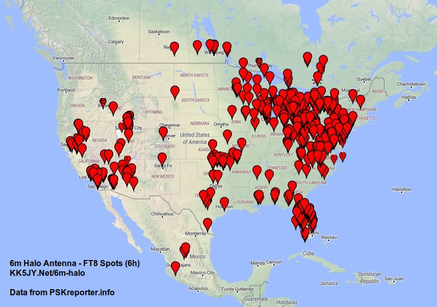 Figure 3: FT8 Spots
(6h)
The first evening on the air, this antenna was able to work coast-to-coast with very
nice signal levels. Some of the received stations bent the S-meter well over
S9. The received reports rivaled those typically seen on HF band openings, with
only 50W of transmitted power applied. Distances in excess of 1,000 miles were
common. Needless to say, it was a very nice band opening.
A map of FT8 spots over 6h of operating is shown at right. These are the stations
that heard me transmitting during that time.
Conclusions
This is a fantastic antenna to start chasing long distance contacts on VHF. The
performance is very respectable, especially considering the antenna size. The
physical construction is simple, and can be done with common hand tools, with
parts available at any local hardware store.
The antenna shown in the picture above was built for about $25 in parts... coax cable
not included. :-)
Copyright (C) 2020 by Matt Roberts, KK5JY.
All Rights Reserved.