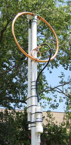
 Small transmitting loop antennas are becoming increasingly popular. Their performance
is quite high considering their physical size, and such antennas have proven successful in
some of my recent experiments. These antennas are easy to tune
when using a remote motor drive, and for most operating, a simple up/down switch at the
control point is enough to quickly adjust the antenna for the current frequency.
Small transmitting loop antennas are becoming increasingly popular. Their performance
is quite high considering their physical size, and such antennas have proven successful in
some of my recent experiments. These antennas are easy to tune
when using a remote motor drive, and for most operating, a simple up/down switch at the
control point is enough to quickly adjust the antenna for the current frequency.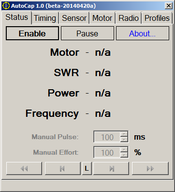 |
| Figure 1a: Status Tab |
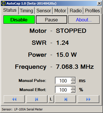 |
| Figure 1b: Status Tab - Operational |
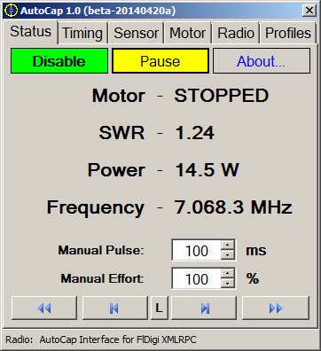 |
| Figure 1c: Status Tab, Operational, but Paused |
| Tip: |
While the software is actively tuning the antenna, you can "hint" to the
algorithm that it should reverse direction by pressing any of the directional
controls. Doing so will cause the automatic tuning process to temporarily
favor the direction you indicate while it searches for a solution. This is
mostly useful if you know that the tuner is searching in the opposite direction
of the best tuning solution, such as might happen when the loop is too far from
the operating frequency for the meter to detect the current SWR slope. If
you are using a radio connection to provide frequency hints, this should not be
necessary, even if you make a large change in operating frequency. See
the Radio Tab section below, for details. |
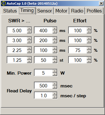 |
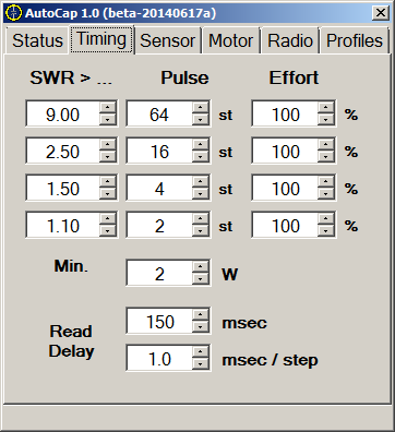
| Figure 2: Timing Tab |
| Tip: |
When using a normal brushed DC motor, braking the motor will allow for smaller Read
Delay values. Unbraked motors will need larger values. I found that when
using an unbraked controller made from relays, the read delay often needed to be nearly
one full second (1000 ms), especially for larger pulse widths. Using the
Arduino-based controller with braking enabled, PWM, and shorter pulses, the read delay
could be as small as 100 to 200 ms, depending on the motor. |
| Tip: |
Using a Radio connection will provide the tuning algorithm with additional data
that it can use to learn how motor actions affect frequency. It may take a few
tuning cycles for it to figure out which direction raises the antenna's resonant
frequency vs. lowering it. Once it has learned which direction is which, the next
time the software needs to make an adjustment, it will have a much better idea which way
to initially turn the motor. This speeds the tuning process and reduces the overall
SWR excursion. |
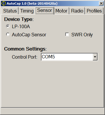 |
| Figure 3: Sensor Tab |
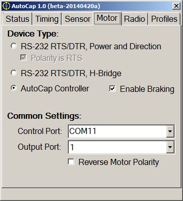 |
| Figure 4: Motor Tab |
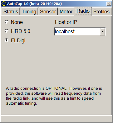 |
| Figure 5: Radio Tab |
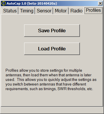 |
| Figure 6: Profiles Tab |
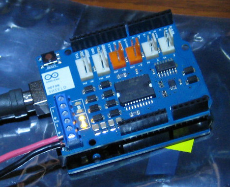 |
| Figure 7: Arduino UNO R3 with Motor Shield |
| Tip: |
If the Arduino is used to control relays, it will still produce more precise
timing control than can be accomplished with the PC-based relays. The type of
hardware attached to the controller depends entirely on the pin assignments made
in the configuration file for the firmware. If the motor shield is omitted,
and relays used, both the polarity/power and H-bridge relay circuits are possible
by properly assigning the output pin numbers, and both circuit types can provide
simple hardware braking if wired properly. |
 |
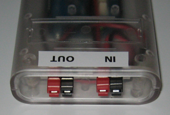 |
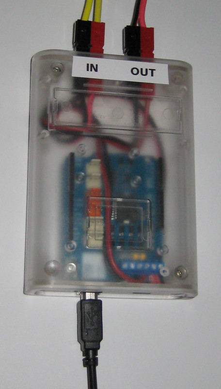
| Figure 8: Finished Interface with Enclosure | |
| Tip: |
The case really only has room to mount two PowerPole connectors. In the
current configuration, that only allows for power input and one motor output
port. It should also be possible to allow the Vin line
from the controller to power the motor, which would allow the power input to be
moved to the coaxial jack on the Arduino, as long as the voltage and current
limits of that connector are strictly observed. This would free the
second PowerPole connector to be used for the second motor port on the Motor
Shield. This would allow the unit to control two motors from a single
USB port. Cutting a custom panel to allow three PowerPole connectors is
also a good option for those with mechanical skills. |
| Tip: |
The case dimensions are such that it will fit one Arduino UNO and one shield,
provided that the shield is mounted nearly flush against the controller.
This was a small challenge, because the Arduino Motor Controller R3 is shipped
with really long header leads. I'm not sure why they did this, but
perhaps they wanted good clearance from the controller board, or wanted you
to be able to easily see the Arduino LEDs even with the shield installed.
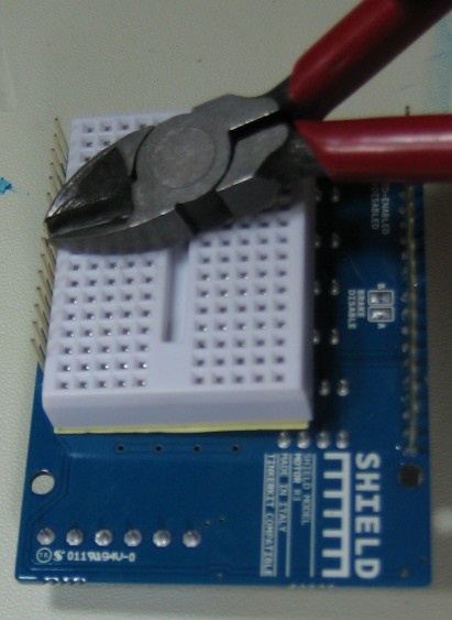
In any case, to make the two boards fit the enclosure, I had to trim the header
leads of the motor board slightly. I found that if I used a small spare
breadboard as a guide on the bottom of the motor board, I could trim the leads
to an almost perfect length, so that everything fit together. The breadboard was simply placed up against each lead to be cut, and flat against the board, and each lead cut to the height matching the thickness of the breadboard. Since this trimming allowed the motor board to sit closer to the controller board, I also had to trim the excess lead length for the screw terminals, to prevent them from getting in the way of the controller's coaxial power connector. CAUTION: If you do any similar trimming to your board, make sure to wear eye protection while you cut! |
|
 |
| Figure 10: Example Stepper Timings |
 |
AutoCap 1.0 Downloads (Click Here) The software and source is being released under the GPL version 3. The license is available on the download page. |
|
Links Small Transmitting Loops - Details of the loops I have built for the contest bands. Serial/USB SWR Meter - A low-cost SWR meter project that works with AutoCap. Arduino - Open-source hardware and embedded development tools. SparkFun - Good source for Arduino and robotics hardware. AdaFruit - Another good source for Arduino hardware. |