
An Updated CW Hardware Interface for FlDigi
Matt Roberts - matt-at-kk5jy-dot-net
Published: 2018-05-31
Updated: 2019-08-27
The Fldigi digital mode software suite supports
a number of modems, including
CW (Morse code telegraphy)
and RTTY. The Fldigi
decoders are some of the best available, making the software an excellent option for
on-air digital operation.
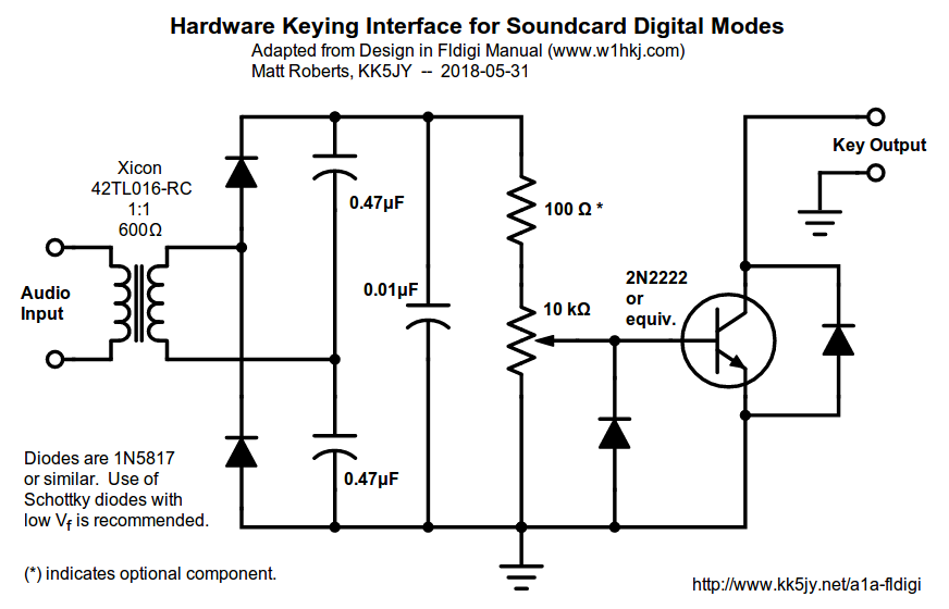 Figure 1: CW Interface Circuit
(click to enlarge)
One of the main challenges when using any digimode software package for CW is that
most HF transcievers only support CW features (e.g., narrow filters, specialized
noise reduction, etc.) when they are used in a dedicated CW mode. For some
radios, this is also true for RTTY operation. In such modes, the radio
typically expects that transmitted elements be supplied via hardware key
closures. Since multipurpose computers tend to not be real-time, generating
a reliable hardware keying waveform from a PC can be a challenege, both in terms
of supporting hardware interfaces, and in generating accurate element timing with
that hardware.
The Fldigi manual describes a
simple hardware circuit
that can easily solve this challenge by converting
sound card CW tones
into key closure signals that can be used to
drive a typical CW transmitter. Using newer versions of Fldigi, the same circuit
can be used to support CW keying,
PTT control,
and
FSK "shift" signals.
The design is solid, but some of the recommended parts—namely the recommended
transformer and germanium diodes—are increasingly difficult to find.
Figure 1 shows an updated version of the circuit using current-production
parts. This circuit has been built and tested using Fldigi, for both CW and
PTT purposes, performing well in a
contesting
environment.
While similar to the original circuit, there are some key improvements:
- The transformer recommended in the manual was replaced with one made by Xicon, with part
#42TL016-RC.
The center-tap pins on each side of the transformer were left disconnected.
There are a number of active-production components that could be used as a
replacement part, but this is one of the least expensive I have found.
Any transformer with reasonable impedance windings, and with a high-end frequency
range of at least 3kHz will work.
- The fixed voltage divider has been replaced by a 10kΩ linear-taper
potentiometer, which allows the signal level provided to the NPN transistor
to be adjusted as needed. If an extra degree of safety is desired for
the base of the transistor, the 100Ω resistor, marked with an asterisk
(*), can be placed above the 10kΩ potentiometer, as shown.
- The diodes were all replaced with
1N5817
Schottky diodes. This is a common part, available from many suppliers
via that part number. This diode has a VF of ~400mV, making
it a great replacement for the diodes in the original circuit, both for the
germanium rectifier diodes, and for the reverse-polarity protection diodes
on either side of the BJT.
The updated circuit otherwise functions just like the original. It is
essentially a voltage multiplier circuit, converting the AC signal from the
sound card into a larger DC signal for driving the
2N2222 NPN small-signal BJT,
which then keys the radio.
This type of circuit is useful for more than just CW, and with more software than just
FlDigi. There are many soundcard mode software packages that support PTT, CW or
RTTY keying using an audio tone, and any of these can be made to control a hardware
input using this device.
Copyright (C) 2018-2019 by Matt Roberts, KK5JY.
All Rights Reserved.