
A Simple Receiver Protection Device
Matt Roberts - matt-at-kk5jy-dot-net
Published: 2019-09-28
Updated: 2025-07-05
When operating on HF from home, I almost always use separate antennas for transmission
and reception. Sometimes, it is also advantageous to run an independent receiver,
that is not part of the transceiver at all, such as an SDR for a panadapter, or a
separate transmiter and receiver for a low-budget or low-power setup. When
using a configuration with independent TX and RX antennas, it is often advantageous
to insert other devices into the signal path of the receiving antenna, such as
preamplifiers or attenuators. In most of these cases, the receiving antenna
system needs to be able to protect its connected devices from strong signals from
the transmitting antenna, to avoid damaging sensitive small-signal components.
There are a number of commercial products on the market for protecting receive-only
components, but some of these tend to be
a bit pricey for my taste.
In fact, spending $100 for a device to protect a
$30 SDR dongle
borders on the absurd, at least to me.
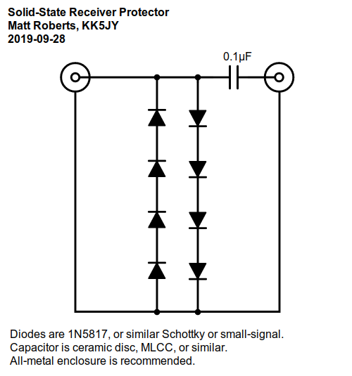 Figure 1
(click to enlarge)
As it turns out, even the pricey commercial protection products
tend
to employ fairly simple circuits that are easy to build from inexpensive components.
Figure 1 shows a schematic of such a device, which I have been using for quite some time
to protect a variety of receiver-related components. It is little more than a
clipper circuit,
designed to pass small-signal RF, while clipping stronger signals.
Each of the two series strings of diodes will clip elevated voltage of one polarity,
so both strings together can clip a sufficiently large alternating
RF voltage. The type and
quantity of diodes stacked in each "leg" of the circuit determines how high of a
voltage can be presented without clipping. The design is simplicity itself.
My favorite diodes for this circuit are very inexpensive
Schottky diodes in the
1N5817
family. These have maximum working voltages in the range of 20V to 40V, a VF
in the range of 0.3 to 0.9V, and an average current capacity of 1A. In a 50Ω
or high-impedance recieve antenna system, these should be more than adequate for
protection against power levels common in the Amateur service. They can be
readily obtained for around $0.10 each (in 2025) in small quantities.
Another very capable diode for HF receiver protection is the
1N4148 "small-signal
switching diode." This part has been available for decades, and is
still very popular because of its low cost and competitive specifications.
The 1N4148 can be obtained for as little as $0.04 each (in 2025) in small quantities.
I have used both of these diodes successfully.
According to the datasheets,
the main electrical differences between them are a higher working voltage
and much lower junction capacitance of the 1N4148, versus the higher working current,
and lower forward voltage of the 1N5817. The 1N5817's design gives it
a faster recovery time, but both diodes are fast enough to operate well into the
VHF range.
Both are also available in
through-hole
packages, which makes them very easy to build into hand-assembled circuits on
typical hobbyist perfboards.
The 1N4148 is probably a better choice for a smaller clipper where there is only
one diode in each "leg" of the circuit. Its smaller junction
capacitance will result in lower attenuation in shorter strings. The 5817 might
be a better choice when using longer strings of several diodes each, since a
lower clipping voltage can be achieved for the same number of diodes. The 5817
might also have a bit of an edge in an environment with very strong RF levels, as when
large transmit amplifiers are used.
There are plenty of other diodes that could be used for such a project, although
many newer diode parts are only available in
SMT packages.
One key design decision that should be considered when building such a device is what
power or voltage level should be considered the "maximum safe" level for
the receiver signal chain. This determines how many diodes need to be stacked
in each "leg" of the "ladder" so that higher voltages are clipped, but lower
voltages are passed unchanged.
E.g., in a typical stack of four diodes per leg (eight diodes total), in a clipper device
using 1N5817 diodes with VF of 0.32V, the point where the device starts to clip
signals is 0.32V x 4 diodes = 1.28V. In a 50Ω system, that corresponds to a
signal level of about 33dBm, give or take variation in the diodes. If a higher or
lower clipping level is desired, the chain of diodes in each leg should be longer or
shorter, respectively. Alternatively, diodes with higher or lower VF
can also be selected to set the clipping point as desired.
For low-gain antennas (such as small loops), a much lower threshold can be used,
since the strongest expected signal levels from the antenna are lower, as is the
pick-up from the transmitting antenna. For higher-gain antennas such as
beams, verticals, dipoles, etc., a higher threshold is usually desired. If the
option is available to place the protection device either before or after an outboard
preamplifier, it should almost always be placed in front of the preamplifier, both to
protect the preamplifier, and to allow the device to use a lower threshold without
clipping.
The units I have built range from one to four diodes in each leg of the ladder.
Some commercial units are more conservative, and use a dozen or more diodes in each
leg. The selection of leg length depends on the intended usage of the device.
The capacitor isn't a required component, but I added it for some extra isolation
from static charges. I normally connect the radio to the connector nearest the
capacitor, so that any static charge from the antenna can drain through the diodes.
If a capacitor is included on one or both sides of the diode ladder, it should be a
ceramic disc, MLCC,
mica, or other
RF-appropriate low-loss type.
For best isolation and shielding performance, the circuit should be enclosed in an
all-metal case of some kind, using panel-mount RF connectors. I use
molded aluminum enclosures that
are roughly 4"x2"x1". These are very durable project boxes, small
enough to produce no noticeable insertion effects, but large enough to accommodate
typical project boards for larger diode ladders. They are also large enough to
easily accommodate bulk-head BNC
or F connectors on the ends
or sides.
While there are other ways to protect a receiver from strong transmitter signals,
these simple devices are a very inexpensive way to get basic protection.
Some cautions are in order, however, when using the receiver protector described
above:
If a receiver installation has issues with strong nearby broadcast transmitters,
the appropriate filter should be placed in front of any diode-based receiver protection
device, to prevent intermodulation distortion from being generated in the diodes.
Similarly, if you use DC bias voltages on receiving antenna lines, e.g., for driving
remote preamplifiers, the DC bias should not be passed through this type of
device. The DC bias voltage injector should have its unbiased receiver port
facing the protection circuit.
This is not a switching device, which means that it cannot be used to
isolate a transmitter from a reciever on a shared feedline. This type of device
is only appropriate for protecting a receiver from overload from a transmitter whose
antenna system is isolated from the receiving antenna system by an appropriate
distance.
Perhaps most importantly, this type of protector should not not be relied
upon as a lightning or EMP
protection device. While diode ladders may provide limited protection
against lower voltage spikes from nearby lightning strikes, the little 1-amp diodes
will quickly fail if substantial impulse energy is presented to the antenna port.
Lightning protection devices have a very different clamping range and method of action,
and should be placed at an appropriate location between the receiver protector and
the antenna system. Both types of devices are appropriate for a receiving
antenna system, and they each play a role in protecting receiving equipment.
Copyright (C) 2019,2021,2024,2025 by Matt Roberts, KK5JY.
All Rights Reserved.