Digital Rotator Controller for Arduino
Matt Roberts - matt-at-kk5jy-dot-net
Updated: 2014-04-18
Part 1 - The Goal (Go to:
Part 2 --
Part 3 --
Part 4)
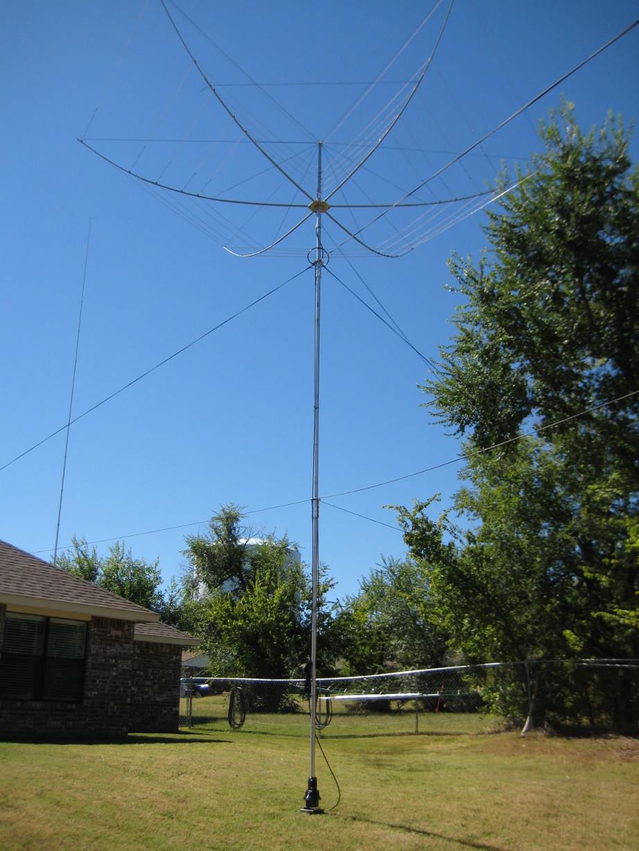
The main HF antenna in my yard these days is a KIO hexbeam. It is mounted on an
aluminum mast at a height of about 23'. The mast is turned by a Yaesu rotor,
sitting on the ground. The antenna performs well for the type of operating
that I do, and the rotor has so far been reliable. However, the Yaesu rotors
still ship with analog controllers, with motor-based azimuth displays. These
controllers are definitely showing their age, and interfacing them to a PC is
rather expensive.
Almost everything in my shack is computer-automated, except for the rotor. The
stock Yaesu rotor/computer interface is about $600, without cables. I wanted
something a little more affordable. K3NG and a team of hams has made some
open-source firmware for the Arduino family of microcontrollers, that will
emulate a Yaesu interface, and provide digital control of a rotor.
The hardware interface he describes is just an add-on to work the up/down buttons
of an existing control head. With some pin assignment tweaks and a relay board,
it is possible to just replace the control head altogether, and use the Arduino
to do everything.
My Hardware
The hardware I chose for the rotor controller consists of these essential
elements:
- The development board, an Arduino
UNO R3.
- The relay board, or "shield", with four SPDT relays. There are
several relay boards available, but I chose the inexpensive
Seeed Relay Shield v1.
- The prototyping shield, with a breadboard attached. There are several of
these available, as well, but this project uses the
SparkFun ProtoScrewShield.
Relay Shield Circuit
Two of the relays were used to build an H-bridge,
which allows for both on/off and directional control of the motor in the rotor. The motor requires
a 24V power supply, which is fed through a MOSFET circuit to one "end" of the H-bridge.
See the Wikipedia page for details on how the bridge works.
The "up" relay was connected to one digital output, and the "down" relay to
another digital output.
Proto Shield Circuit
The MOSFET is driven by a PWM output from
the controller board. This allows the microcontroller to pulse the FET, which in turn pulses the 24V
power supply, producing a square wave signal of varying duty cycle, which drives the motor with a
varying level of power. This allows the controller to soft-start and soft-stop the motor, reducing
the amount of "bounce" or "jerk" exerted by the rotor onto the mast. An
example of such a circuit is described in a
tutorial at bildr.org.
That tutorial also describes the use of a
flyback diode in the motor circuit, which I did
not use here. The reason is that the motor has to be reversible, so I can't place the diode across
the motor contacts. I could place the diode across the FET output, but if you look at the
example circuit for the H-bridge, you will notice that when relays are used, the bridge circuit will
automatically quench flyback voltage when the motor is powered off. This is because the motor, when
at rest, is shorted out by the H-bridge. This provides braking and flyback protection basically for
free.
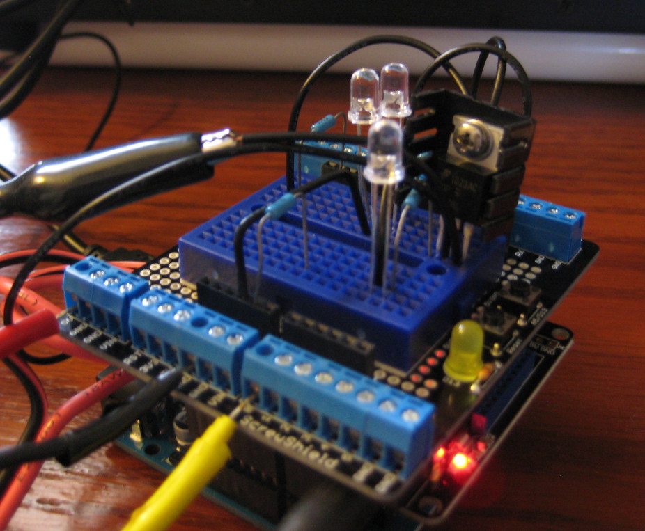
I added some LEDs to the circuit to show me when the motor was turning CW (green) or CCW (red).
Another LED was used to show the PWM output. This LED gets brighter as the PWM duty cycle rises,
and dimmer as the PWM duty cycle falls. The proto shield has an LED that blinks when D13 goes
high from the CPU, and this was used to indicate serial activity.
Power Supplies
The relay board uses a 7-9V supply. The rotor requires 24V at 500mA. The CPU board can be
powered by the USB port.
Rotor Position
The rotor position is reported through a 500-ohm potentiometer located in the rotor housing.
The outer legs of the potentiometer were connected to +5V and GND on the controller board, and
the wiper connected to A0. The CPU reads the voltage at A0, and translates that to an
azimuth/heading. At 5V, the resistor dissipates 10mA, which is small enough that a buffer
circuit was not needed.
Calibration
The most time-consuming step for me was the calibration. The calibration is well documented
in the comments of the K3NG source file, but for some reason I initially read them
incorrectly. Once I realized what I needed to do, the calibration was straightforward. The
entire process can be done from a serial terminal, and the results are stored in the EEPROM of the
controller. I chose a 360-degree pattern (no overlap), centered to the south (180°).
Operation
I did the build-up in two stages. The first stage used only the relays, and the second stage
added the MOSFET and PWM control. The controller works fine without the proto board and the
MOSFET, as the relays can handle the switching on their own.
After adding the FET switching circuit, I found that the soft-start seems to work better than
the soft-stop, but I think I see why, as the soft-stop only ramps down to about 50% duty cycle,
whereas the soft-start goes smoothly from zero to full power. At first, I thought there might
be a bug in the firmware, but it turns out there are some tuning parameters in the source file
that let you control the smoothing during soft-stop. Even using the defaults, the PWM-damped
rotor motion is much more smooth than with the stock controller. After tinkering with the
parameters, I can get the soft-stop even softer, and it does a better job of stopping on a
specific heading than it did before.
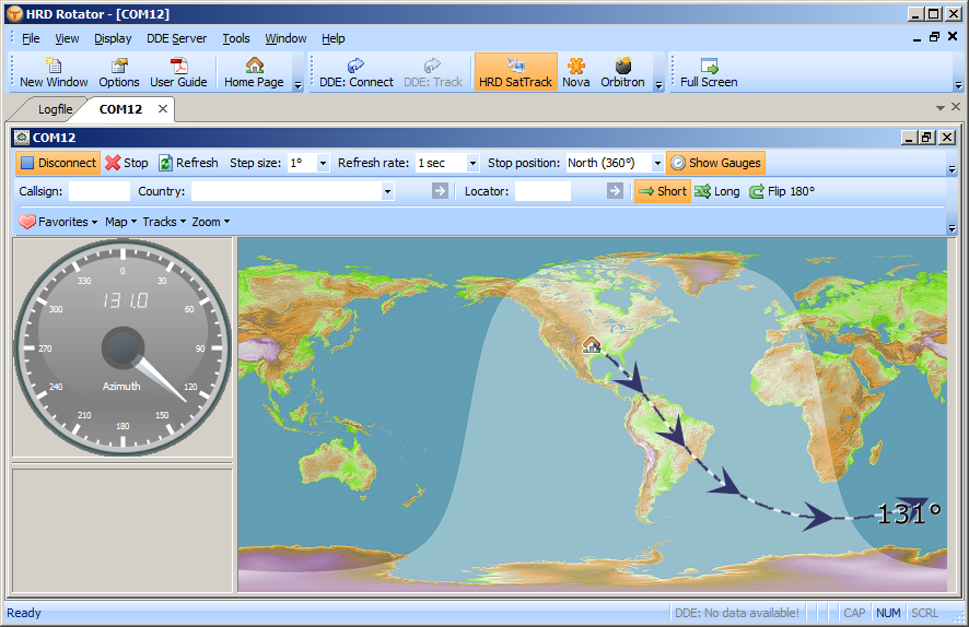
I had to adjust the default data rate for the controller to 9600bps in order to use it with HRD,
which doesn't support K3ND's default of 115200bps. HRD 5.0 has a rotor control program, that
worked fine with the controller, and I can now double-click anywhere on the planet and have
the rotor automatically point at that location.
The Inexpensive and Flexible Option
Yaesu wants $600 for a control module with an RS-232 output. The most popular after-market
model is the Green Herron, which is about the same price. The Arduino Uno R3 was $30, the
relay board was $20, the prototype board on the top was $15, the MOSFET w/ heatsink was $2,
and there's probably another $1 in connectors, wires, resistors and LEDs on the board for
my amusement. And the Arduino is USB, not RS-232. And I have the source code to tinker
with. I'm using a couple of small UPS batteries for the 24V power supply, so in fairness,
the cost of a power supply that can do 500mA should probably be included in that.
And LCD display, up/down buttons, and case would be another $30 or so.
So for around $70, I have a working controller circuit that can easily be duplicated into
a nice desktop enclosure.
The wiring for the prototype is a bit of a mess, but it was still a fun project.
Part 2 - The Sequel! (2014-03-08)
The experiments described above worked quite well, but there were still some small bugs in
the firmware that were a problem for me. I set out to dig into the code and
figure out what was up. I also didn't like the relay solution, since there are
really nice solid-state H-bridge parts that can do the job better. But first a
discussion of the bugs...
The Bug List
First, the soft-start and soft-stop would occasionally cause the rotation to get
"stuck" between start and stop, especially when issuing a move command to
an azimuth target that was close to the starting azimuth. The firmware just didn't
seem to cope well when the soft-start window overlapped or touched the soft-stop
window.
Second, the rotor I have is oversized for my antenna load, so there is a bit
of "bounce" in the rotation, as the rotor spins up or down. This
causes the azimuth feedback voltage to oscillate slightly around the current azimuth while
the mast is moving. This is normal for all but the most heavily-loaded rotor
and antenna assemblies, but when I set the target tolerance of the firmware to something
small (e.g., one degree), as the rotor started to slow down and get close to a rotation
target, the PWM output voltage would start to jump up and down right before the mast
finally came to a stop. This jerked the mast around a bit, and can't be good
for the motor life in the long run.
After experimenting with the code, I believe I have fixed both of these issues, and
the fixes are very simple. I will post patches below.
Hardware and Firmware Changes - Disclaimer
Below, I will describe the changes I made to my hardware and firmware configuration to
achieve acceptable results on my own system. BUT BE WARNED: If you
choose to copy these or use them for inspiration, you do so at your own risk.
Just because it works for me, doesn't me it will work for you. If you try any of
this and something breaks, or your antenna falls over, or your hardware goes up in
smoke, etc., don't blame me -- you have been forewarned. This information comes
as-is, with absolutely no warranty of any kind.
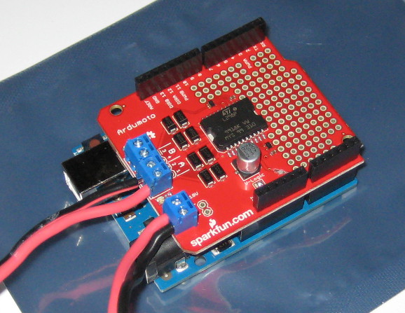
Hardware Changes
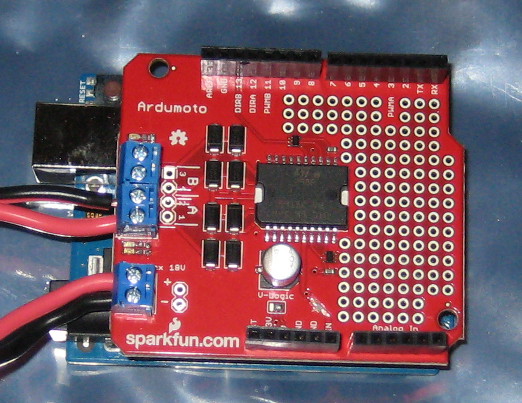
Before debugging the firmware, I made a hardware change. The relay board was replaced
with a SparkFun
Ardumoto shield. A standard
Arduino motor shield would have
done just as well, but since I don't need the braking function (which is already provided
mechanically within the rotor unit itself), I decided to use the slightly-cheaper SparkFun
motor board. And I just happened to have an unused one handy. Configuring the
firmware to use the board was straightforward, as only two digital I/O lines are used, one
for PWM, and the other for direction. However, this board was also
modified in two ways.
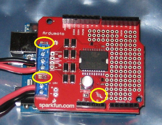
First of all, the Ardumoto board has a trace that links the Vin connector blocks
to the Vin lead of the controller. That means that the board can only
use a motor voltage source that is within the input voltage range of the controller's onboard
voltage regulator, nominally 10-12V, depending on the specific board. I cut this
trace as shown below, to separate the Vin connector of the motor board
from the corresponding Arduino header line. That allowed me to use the full voltage range
of the L298 chip
on the motor board, which I needed to drive the 24V motor in the rotor. The L298
actually has two different power supply sources: one is the "high voltage" side, which
was connected to the trace I trimmed. This voltage is run through the H-bridge transistors to
power the motor. The other side of the L298 is the "logic level" side, which
is supplied by other header pins from the controller. This is the voltage that is used to
interface with the control electronics driving the H-bridge.
Since the LED dropping resistors on the motor board were similarly sized for ~12V, I also removed
those resistors to avoid destroying the LEDs when 24V was applied. I could have installed
resistors appropriate for 24V operation, but chose not to, since I won't be able to see the LEDs,
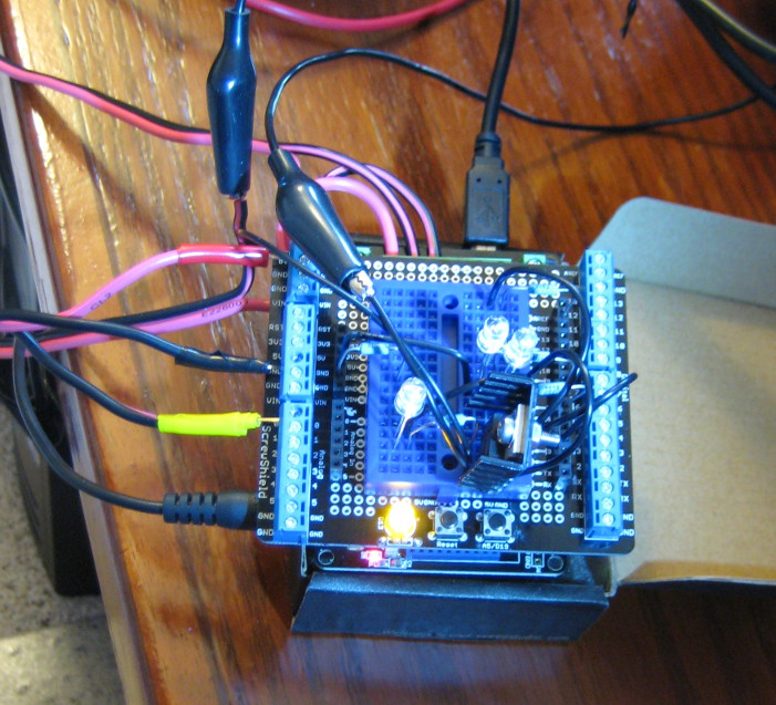
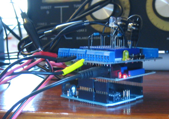
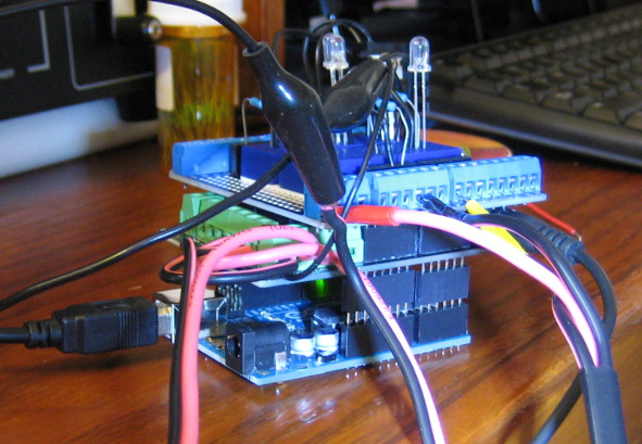
anyway. The location of the changes is noted in the images below:
The images above show the same view, but the second one highlights the board change locations.
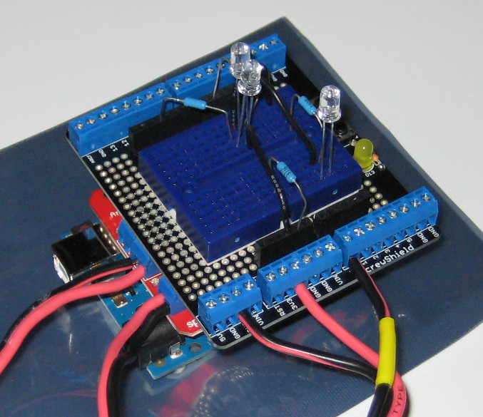
The same proto-board was used on the top of the Arduino "stack" to add LEDs and
to connect the potentiometer of the rotor to the analog input of the controller, with some
updates:
Above, from left to right:
- Arduino UNO with SpartkFun motor shield
- Original proto-board stacked, with FET removed
- Updated proto-board stacked, with new LEDs and buttons
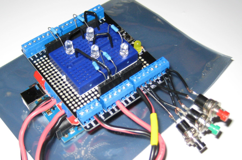
I took the opportunity to clean up the wiring a bit, and update the user interface
configuration. There are now a total of five LEDs, and three buttons for
manual control and monitoring. All of these are supported features of the
stock K3NG code base:
- Red LED - indicates CCW rotation
- Green LED - indicates CW rotation
- Red Button - causes CCW rotation until released
- Green Button - causes CW rotation until released
- Black Button - stops any pending rotation immediately
- Blue LED - indicates that the controller's 3.3V power supply is running; effectively, a "Power" LED
- Yellow LED on proto-board - indicates USB/serial port activity
- Yellow LED on breadboard - indicates PWM intensity, either direction
Firmware Changes
I also made some changes to the stock K3NG firmware. I identified two items above
that I believe are bugs related to my specific configuration, which used a single PWM
pin for both CW and CCW operation, and also enabled both the slow-start and slow-stop
features.
The first bug appears to be caused by a state transition check that allows the slow-stop
code to activate before the slow-start code completes. There are a couple of
different ways to fix this, but I chose the easy way, which was simply to prevent the
slow-stop code from activating until the slow-start code had completed its ramp to full
rotor voltage. On or about line 5311 of the INO file, there is a section that
looks like this:
   // normal -------------------------------------------------------------------------------------------------------------------
   // if slow down is enabled, see if we're ready to go into slowdown
   if (((az_state == NORMAL_CW) || (az_state == SLOW_START_CW) || (az_state == NORMAL_CCW) || (az_state == SLOW_START_CCW)) &&
        (az_request_queue_state == IN_PROGRESS_TO_TARGET) && az_slowdown_active && (abs((target_raw_azimuth - raw_azimuth)/HEADING_MULTIPLIER) <= SLOW_DOWN_BEFORE_TARGET_AZ))  {
   #ifdef DEBUG_SERVICE_ROTATION
   if (debug_mode) {Serial.print(F("service_rotation: SLOW_DOWN_C"));}
I simply changed the if statement to read like this:
   // normal -------------------------------------------------------------------------------------------------------------------
   // if slow down is enabled, see if we're ready to go into slowdown
   if (((az_state == NORMAL_CW) || (az_state == NORMAL_CCW)) &&
        (az_request_queue_state == IN_PROGRESS_TO_TARGET) && az_slowdown_active && (abs((target_raw_azimuth - raw_azimuth)/HEADING_MULTIPLIER) <= SLOW_DOWN_BEFORE_TARGET_AZ))  {
   #ifdef DEBUG_SERVICE_ROTATION
   if (debug_mode) {Serial.print(F("service_rotation: SLOW_DOWN_C"));}
I see why the K3NG team used the original checks, as they are trying to avoid a long
slow-start ramp that causes the rotor to overshoot an azimuth target close to the
starting azimuth. However, in order for that to work, the rotor still has to develop
enough torque in the ramp-up, to be able to actually move to its target. This is the
item that appears to be missing. An alternative "fix" might be to
simply set the PWM line to some minimum voltage when doing an early transition from slow-start
to slow-start. The slow-stop minimum voltage would probably be a good value for such a fix.
Even for small moves (e.g., five degrees), the change shown above allowed for very
precise azimuth changes to be made. The ramp up/down allowed me to change the
AZIMUTH_TOLERANCE (on or about line 581) to 1.0 degrees, and the rotor actually
achieves that level of precision. I am using a slow-start time of 1.0 seconds,
which is sufficient for my light antenna load. This was a very effective
refinement of the rotor control.
The second bug appeared to be caused by a decrementing counter that is used to compute
the PWM step-down as the rotor azimuth angle approaches its assigned target during a
"move" command. The counter appears to occasionally step down past zero,
into negative values, causing unexpected PWM behavior. Fixing this involved testing
the counter before decrementing it, which occurs in two locations. On or about line
5264, and again on or about line 5305, there is a line that looks like this:
az_slow_down_step--;
I just changed that line to look like this:
   if (az_slow_down_step > 0)
      az_slow_down_step--;
That prevents the counter from decrementing if it is already zero. That seems to have
cured the jumpiness of the PWM line as the antenna bounces towards the target azimuth.
Part 2 - Conclusions
Combining the changes above with some normal tuning of the numeric parameters within
the INO and Features files, the rotor controller appears to behave much more consistently
and smoothly. When using the updated firmware with Ham Radio Deluxe 5.0's
Rotator software, the rotor turns towards targets smoothly, and stops within +/- 1.0
degrees of each target. That is exactly what I wanted for my rotor, and the
K3NG team did a great job getting us a solution for Arduino that is both feature-rich
and inexpensive.
The motor board is a fantastic addition to the project. It is slightly more
costly than the relay board, but it operates silently, and isn't subject to mechanical
wear. Even after numerous rotor movements, and several minutes of operating,
the L298 chip was just barely warm to the touch. My rotor pulls 0.5A steady
state at 24V, so that's not bad. My only complaint about all the L298
shields on the market is that they place an artificial limit on the motor supply voltage,
by either tying the voltage supply line to an Arduino header pin, or sizing the LED
resistors for 12V, or both. There are some external L298-based motor I/O
boards that would work just as well for this project, and they do not have such a
limitation. One that comes to mind is
one from CanaKit, which allows for
supplies up to about 36V. That's much closer to the L298's stated limit of 46V.
The proto-board circuit was simplified significantly by removing the FET. Since
the PWM current-switching function was moved into the H-bridge, there was no need for
it. The proto-board now only has the LEDs, and associated resistors, and
control buttons. Trading the relay board and FET for the motor shield was
probably close to a break-even in terms of overall system cost.
The new circuit also simplified the power supply needs. The first version of the hardware
required three different power supplies: one for the Arduino via USB, one for the relay board,
and the 24V supply for the motor. With the relays gone, the Arduino runs from USB, and the
rotor from the 24V supply. This means only one external voltage supply is needed.
The next step is to add an LCD display.
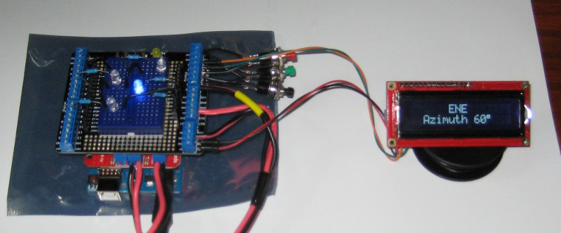
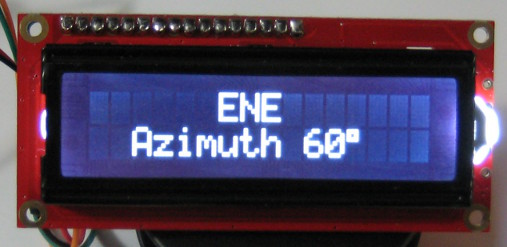
Part 3 - An I2C LCD Display
Using HRD to control the rotor was satisfactory for my purposes, but the K3NG software
also supports using an LCD display to show the current azimuth, movement command, and
rotation target. That sounded like a nice capstone to the project, so here
goes.
Hardware
There are code samples in the INO sketch file for several LCD types. I wanted a nice
display, but there are only so many free I/O lines left on the controller, so I opted for
a unique combination that required small modifications to the code. The LCD selected
is a 16x2 white-on-black inverted
character display from SparkFun. This is a very attractive display that
shows white characters that stand out on a black background, rather than the usual
black letters on a light colored background. In order to avoid using up
several GPIO lines for the display, I added an I2C adapter board, called
a "backpack" that handles the parallel interface to the LCD, and makes it
available as a two-wire I2C device to the Arduino's TWI/I2C
pins. There are also several of these to choose from, but I picked up the very
inexpensive
AdaFruit backpack.
After soldering together the display and backpack, connection to the Arduino board is
quite simple. The I2C interface on the UNO R3 is pins A4 and A5.
These are the SDA (data) and SCL (clock) lines. Besides these, the display
only needs +5V and GND connections, and the LCD installation is complete.
One more minor item I added to this version of the hardware has to do with the A/D
input for heading. Even when the rotor assembly is completely still, I
noticed that the A/D input value has some jitter. To fix this, I added
a 4.7uF capacitor across the V+ and GND wires that feed the potentiometer.
While working on another project, I had noticed that the 5V power supply of the
Arduino can be a little noisy. So adding a filter capacitor to the power
lines that feed the potentiometer smoothed the A/D voltage considerably. I
also noticed that the go-to stopping position accuracy was further improved after this
change, as well as the smoothness of the soft-stop ramp.
Software
The K3NG software required a slight modification to work with the recommended AdaFruit
libraries. Once those libraries were installed, two additions were made to
support that library. First, a new LCD section was added, creating the
required lcd object. This is slightly different than a standard
LiquidCrystal instance, because the constructor only takes a single argument,
which is the I2C address of the LCD backpack device. Second,
code was added to properly enable the LCD's LED backlight, which is also handled in
a slightly different manner than typical displays.
The first code change occurs at or about line 227, where this section is added:
/* uncomment this section for an Adafruit (non-RGB) backpacked LCD */
#define FEATURE_LCD_DISPLAY
#define FEATURE_I2C_LCD
#include
#include
#define AF_I2C_ADDRESS (0x00)
#define BACKLIGHT_STATE (HIGH)
LiquidCrystal lcd = LiquidCrystal((uint8_t)(AF_I2C_ADDRESS));
The AdaFruit backpack has some board-level solder jumpers that allow its address
to be set. By default, its address is zero (0x00).
The second code change then occurs at or about line 745, where this block is modified,
with the bold lines being added:
#ifdef FEATURE_I2C_LCD
#define RED 0x1
#define YELLOW 0x3
#define GREEN 0x2
#define TEAL 0x6
#define BLUE 0x4
#define VIOLET 0x5
#define WHITE 0x7
#ifdef BACKLIGHT_STATE
byte lcdcolor = BACKLIGHT_STATE;	// default backlight value
#else
byte lcdcolor = GREEN;  // default color of I2C LCD display
#endif
#endif //FEATURE_I2C_LCD
#endif //FEATURE_LCD_DISPLAY
These are minor changes, but the result was a nice summary display of the current
rotor state, that was independent of the software running on the PC.
The next step is an enclosure, to finish off the project.
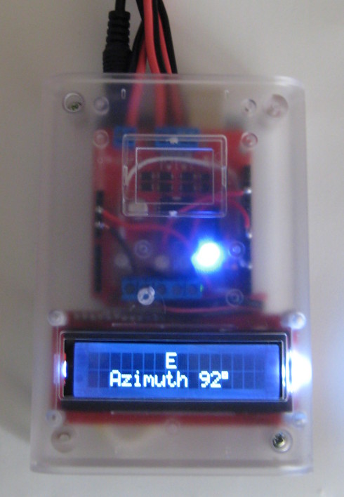
Part 4 - The Enclosure
The rotor controller will be an ongoing part of my operating desk, so I want
it in some kind of enclosure to protect it from damage. The enclosure
I tried had just enough space to fit in the controller board and the motor control
board.
In the iamge above, you can see the assembled enclosure, with the blue
"power" LED glowing internally. There are four LEDs
in the finished device, one for power, one for PWM effort, and one each
for left and right.
The LEDs are mounted on the perf space on the motor board, along with five
screw terminal blocks for connecting to the potentiometer and display.
This allowed me to eliminate the proto board from the stack of shields.
The enclosure is clear plastic, which allows all of the circuits and wiring
to be visible from the outside. So the project retains its
"kit-like" appearance, but still has no exposed circuits.
For now, I have opted to leave off the buttons, as they have little use for
me, but the enclosure has enough room to mount buttons at a couple of
different locations, should they be needed.
This is probably the last update for this project. It's time to
work on something else for a while.
73!