While discussing simple and easy Field Day antennas
with a local ham, I happened to remember a design
that I had seen in the ARRL Antenna Book many years ago. The design had interested
me at the time, and I even modeled it in EZNEC+, but I never built it, because I had other
antenna designs for 20m that were already working well for me.
My friend, however, didn't have an effective antenna for 20m, as most of his work is on 40m
during the evenings. Since he wanted a dedicated 20m antenna for Field Day and other
weekend events, he decided to build the design from my model. As it turns out, the
antnena is every bit as effective as the model suggests, and can be built for a few dollars
in just about any yard.
The design was originally suggested in a September 1984 QST
article, by K8CH. The idea is simple enough — hang a wire vertical from a support,
using two elevated but sloped radials to form a basic "ground plane" antenna.
Since the radials are elevated, the ground losses are minimized, even though there are only
two of them.
The Model
I rarely build any HF antenna unless I model it first. Neither will I recommend one to
others without being able to show the theoretical performance in a computer model. The
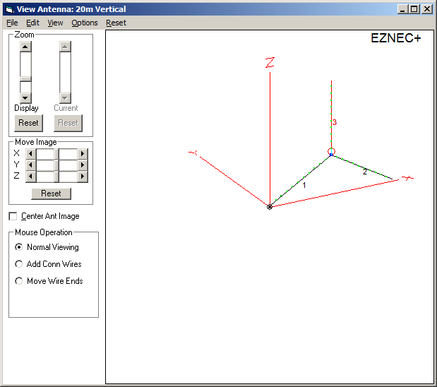
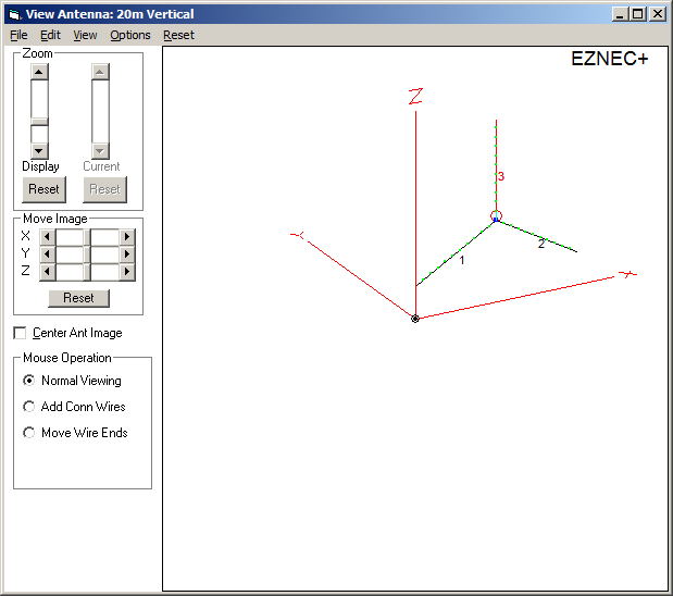
model for the K8CH antenna, scaled for 20m, is shown below:
Figure 1: EZ-NEC+ Model and Data Peak at 25'
The model assumes the peak of the antenna is at a very reasonable 25' above the ground,
which is an elevation that anyone should be able to achieve. This results in radials that
are roughly 6" above the ground at the tips, and a feedpoint at about 8.5'.
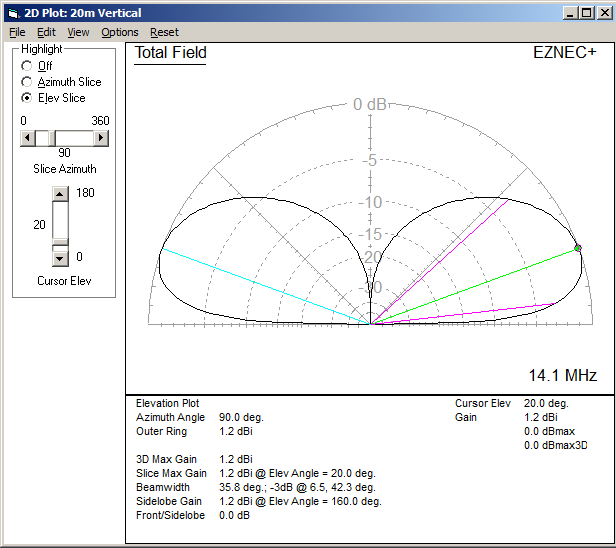
By raising the antenna to 30', a modest improvement in pattern, elevation angle, and 50-ohm
match can be realized, bringing all three close to optimal values, as shown in Figure 2:
Figure 2: EZ-NEC+ Model and Data Peak at 30'
Either antenna is a good match to 50-ohm feedline, which should be directly attached.
As with all such antennas, a choke at the base is recommended.
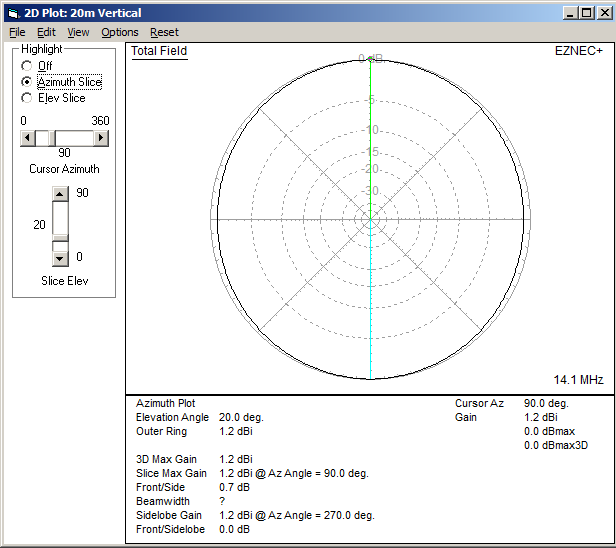
Note that the eccentricity (the front/side ratio) in the azimuth plane
is less than one dB for each antenna, increasing slightly with
increasing height above ground.
This type of antenna can work with any band, provided that a support of sufficient height
is available. The original design by K8CH was for 30m, and was hung from a tree.
Each wire in the vertical is λ/4 long, adjusted for insulation, if needed.
The angle between each wire is roughly 120°, although this can be adjusted to improve
the feedline match, as needed.
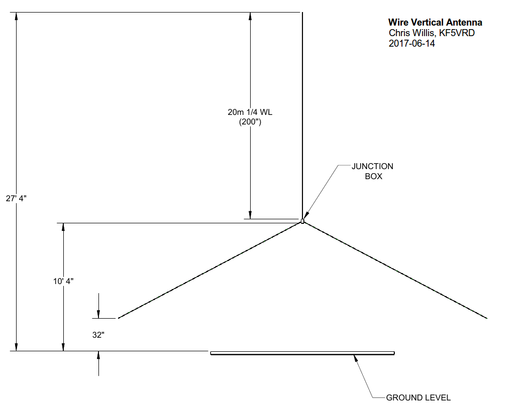
When Chris installed the antenna at his residence, he split the difference between the two
models above, installing the antenna peak at just over 27', as shown in Figure 3,
resulting in a feedpoint match very close to the model prediction:
Figure 3: KF5VRD 20m Vertical As Installed - Peak at 27'4"
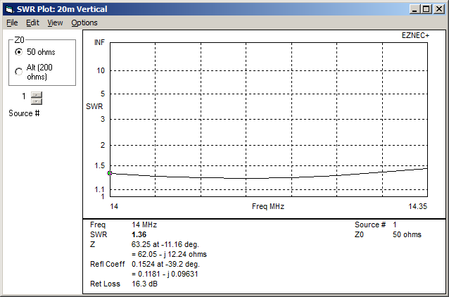
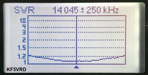
Figure 4: AA-30 SWR Sweep of the Antenna
Field Day 2017 20m Contacts
Trial Run
He used PSK31 as his first test of the antenna, running QRP from his KX3. One of the
first 20m contacts he made was R6AV on the
northeast coast of the Black Sea. Given the conditions at the time (SFI = 73; SSN = 11),
the antenna immediately demonstrated its DX prowess and efficiency.
The real test of the antenna was ARRL Field Day 2017.
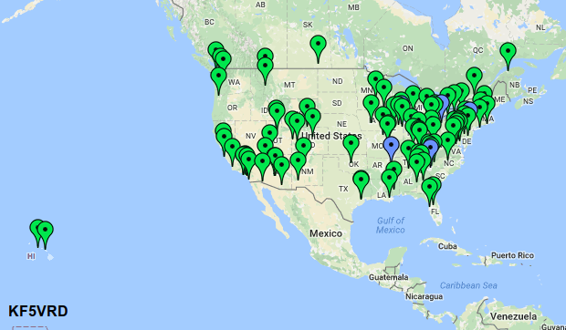
During that event, the antenna netted 101 20m CW contacts, using 5W or less. Among those
contacts were KH6J and
KH6RS in Hawaii. A map of the 20m FD 2017
contacts from KF5VRD is shown at right.
Even running less than 5W, this antenna is an effective communicator.
Installation Considerations
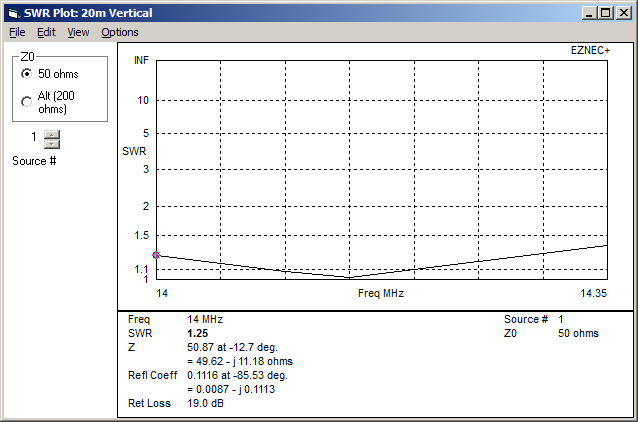
The antenna is a good match for 50-ohm feedline, as the sloped radials raise the impedance
from the 36-ohm theoretical value. The slope can be adjusted as needed to obtain the
best match to the cable. As a full-size antenna, the design has a very flat SWR over
a wide bandwidth, as shown in Figure 4.
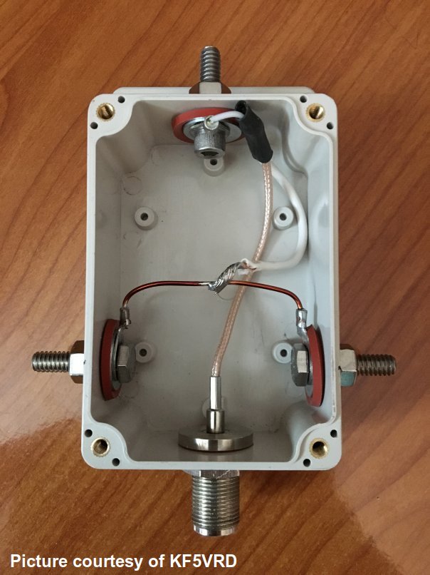
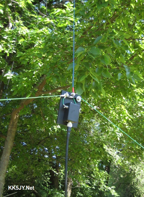
The feedpoint can be assembled in any number of ways. Chris likes outdoor enclosures
for his ham gear, so he built a
junction box
to connect the wires to the coax. The box had three 1/4" stainless fasteners
for the wires, and a waterproof
N connector for the coaxial
cable. You can also see the orange silicone washers he used to weatherproof
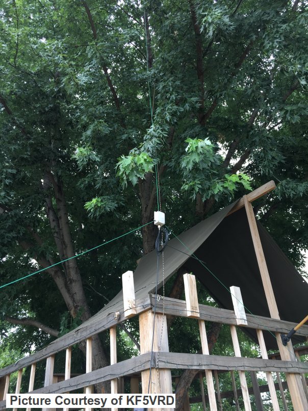
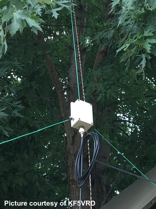
the holes where the studs pass through the walls of the box. Figure 5
shows the antenna pulled into a tree next to a treehouse, and a closeup of the
junction box.
Figure 5: Installed Antenna
The coil of coaxial cable underneath the box is a common-mode choke, which is a good addition
to just about any HF antenna. Even though the antenna is a good match for the 50-ohm
cable, a choke virtually eliminates any common-mode current that might try to flow due to
environmental interactions or cable lengths that happen to be a multiple of 1/4 λ in length.
I build a copy of this antenna at my own house a few years later, and made a couple of
mechanical changes while I was at it. First, I included the choke as part of the
feedpoint enclosure, as shown in Figure 6. The choke is a
Balun Designs Model 1110
with studs installed on one end, and mounted on the matching
dipole plate.
This provides an enclosure, N connector, choke, and a place to connect the wires in a single package.
I used 1/4" hardware to connect the antenna wires.
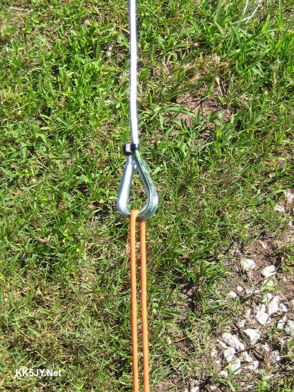
The updated antenna also uses looped wire ends, with
thimbles installed to
avoid damaging the wire when it is pulled taut. The wire is looped around the
thimble, and then back on itself. The wire can be held in place using tape,
zip-ties, or small saddle clamps. This allows easy adjustment for tuning,
since the length can be changed by simply detaching the tape or ties, and moving
the thimble in or out, as needed.
Figure 6: Updated Antenna
Care should be taken when locating the radial anchors. If the anchors
are attached to the ground, they should be located such that they do not
present a tripping hazard to people or animals. If more than QRP
is used, the ends of the radial wires should be insulated, to prevent
people or animals from coming in contact with an energized conductor.
While the voltages present at the end of a quarter-wavelength radial are not
excessive, even at QRO, they are high enough to cause RF burns if touched.
The rope used to attach the radials to the ground should have good insulating
properties. Alternatively, ceramic insulators could be used between
each radial and its support rope. The ends of the radial conductors
should not be allowed to touch the ground (or anything else).
Like all vertical antennas, installation height matters. This is
particularly true of elevated-radial antennas. Placing the radials
too close to the ground increases ground losses, and lowers the efficiency
of the antenna. Raising the antenna too high causes secondary lobes
to form, raising the peak elevation angle, which reduces the antnena's DX
capabilities. The antenna dimensions shown in Figure 3 are
close to optimal, and can be scaled for use on other bands. Many
hams have been told that "higher is better" but this is not
true of vertical antennas. One nice feature of this design is
that the optimal height happens to be close to the lowest reasonable
height that will allow the ends of the antenna's radials to be kept
above the ground. Since most of the radial current is concentrated
near the feedpoint, the ground losses are minimized, even though the ends
are fairly close to the ground.
Advantages
The elevated radials greatly reduce ground losses when compared to a
ground-mounted vertical antenna. The antenna is resonant and a
good match for 50-ohm cable; it can be easily adjusted for the best
match to eliminate the need for extra tuning devices, like shunt
inductors.
Figure 7
The antenna is lightweight, and can be quickly deployed for portable
operation, when adequate supports are available. The
antenna's "flat" profile allows it to be easily located
in areas where other antennas might not fit, e.g., behind a stand of
trees, or along a fence line of a suburban property. If proper
colors are chosen when selecting materials, this type of antenna can
be made very stealthy, even when not hidden by trees or other natural
visual barriers.
More Support Ideas
A mature tree with stable branches near 40' could support an antenna
built for 40m or shorter wavelengths. Temporary supports, such
as fiberglass masts, are ideal for this kind of antenna, since most
of the height of the antenna does not generate additional wind load.
Supports used for the vertical element do need to be nonconductive,
to prevent coupling to the wire being supported.
If there are no trees or other supporting structures available, the
vertical element can be made self-supporting by using metal tubing or
mobile antenna components. In Figure 7 is a picture of a
recent prototype I built using half-inch aluminum mobile antenna
mast. The vertical element was 11' long for use on 15m.
Other forms of rigid tubing would work here, and could even extend
to significant height if guying is used.
The feed point for this antenna was roughly 10' above the ground, suppored
by a short fiberglass mast. This could just as easily be done with a
length of treated lumber, or a piece of galvanized top-rail, such as is
used for chain-link fence. Supporting the antenna from the bottom
can be done with either conductive or nonconductive material.
Interesting Variations
While the two-radial antenna is easy to squeeze into tight spaces, three radials
can be spaced out and used as guys lines, as well. A fiberglass mast, guyed
by the radials, makes an antenna that can be raised anywhere, trees or not.
Adding a third radial, and with the radials spaced equally from each other,
also removes the azimuth eccentricity from the pattern.
In either the two- or three-radial configuration, this type of antenna is an
effective teammate for remote antenna tuners, such as those from SGC or MFJ.
I recently built a three-radial antenna, cut for 15m, and then mated it to
an SG-230, mounted
just above the radials on a fiberglass mast. Not only did the antenna
tune up well on all HF bands, but it worked a long string of DX on both 15m and
20m. Maps of spots over 24 hours for each band are shown in Figure 8.
Figure 8: 15m and 20m Spots
Conclusions
The performance of the antenna is without question. Even running QRP, the antenna is efficient
enough, and with a low angle of radiation, that it works DX with ease. As an unloaded wire
antenna, it should be able to withstand any legal-limit power level. The only power constraint
would be in the feedline chosen.