The Ladder Line Antenna
Matt Roberts - matt-at-kk5jy-dot-net
Published: 2021-05-05
Updated: 2024-02-08
If you build enough antenna projects, you will eventually collect plenty of spare parts and
components. I have no shortage of such project debris at my house, including generous
piles of wire and feedline.
For some time now, I have been looking at segments of hand-made
ladder line hanging idle
on my fence, wondering if it could be used for anything interesting. The feedlines
are of high-quality, and have resisted many years of weather, but I simply have no use
for them anymore.
Just for fun, I entered the dimensions into EZNEC+,
to see what kind of antenna patterns could be produced by using a length of ladder
line as an antenna, feeding and/or terminating it in various ways. Ladder
line encloses enough area to make an effective receiving loop antenna for HF,
but it can also do more interesting things.
Below is a discussion of using lengths of ladder line as a receiving antenna for the
HF and MF bands. For convenience, the resulting antenna will be called a
"ladder line antenna," or LLA. Depending on how the antenna
is wired, it can be unidirecitonal, bidirectional, or omnidirectional.
The Model
To make a directional antenna out of a piece of ladder line, the circuit is simple: the
ladder line is fed directly from one end, using a proper beverage antenna transformer to
adapt the coaxial cable to the much higher Z0 of the ladder line. The
other end is terminated using a non-inductive resistor. The entire antenna is elevated
a few feet off the ground, and the plane of the ladder line is held vertical.
The resulting antenna has an end-fire main lobe, pointing off the feedline end of
the ladder. This means the direction of an LLA is the reverse of a typical long
beverage antenna, which has its main lobe off the terminated end.
To make the same antenna bidirectional, similar to the SRL and
LoG antennas, the terminating resistor is replaced by a short circuit,
forming a continuous loop of wire. To make an omnidirectional LLA, similar to a
vertical antenna, the terminating resistor is removed, leaving an open circuit at
the end opposite the feedpoint. Since all of these changes can be made at the
termination end of the LLA, converting between uni-, bi-, or omnidirectional configurations
on a single antenna could be done with switches or relays.
As with many receiving loop antenna designs, the LLA is broadband, and if the length
is selected carefully, it can be used unmodified on multiple bands. Unlike many
of my other loop antennas, however, the terminated (unidirectional) LLA is impedance-matched
to the coax. Like its beverage cousins, the terminated LLA uses the termination
resistor to maintain a near-uniform impedance along the length of the antenna and into
the matching transformer.
The length of the LLA is a trade-off between signal levels captured, and pattern beamwidth
on shorter wavelengths — a trade-off that is not uncommon with loop antennas.
Through some experimentation, I found that a 33' terminated LLA has a useful pattern for
wavelengths of 40m and longer, while a 50' LLA is useful for wavelengths of 80m and
longer. Such an antenna is not limited to long wavelengths, however. Shorter
LLAs can produce directional patterns on 20m and shorter wavelengths.
According to the models, a length of λ / 4 is a good target for a terminated
LLA on the shortest wavelength to be used on that antenna. A longer LLA starts
to "crush" the peak of the main lobe in the azimuth plane. For a bidirectional
LLA with a shorted termination end, that figure is closer to λ / 8.
Also according to the models, the best terminating resistor value is roughly that which
will match the Z0 of the ladder. For my 3.5"-spaced ladder, a
470Ω resistor produced the best overall patterns. This is a typical spacing
for commercially-produced ladder line products, but other spacings can be easily made
if desired. Wider or narrower ladders will likely require a different termination
value. A wider ladder should generate more power output to the receiver per linear
foot of line, since it encloses more are, since it encloses more area.
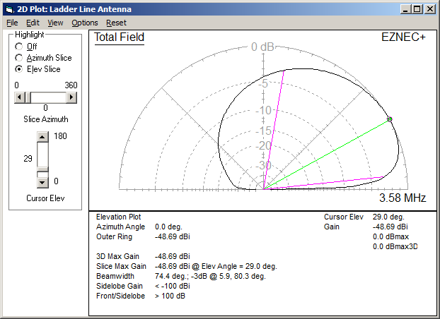
Figure 1: 33' LLA on 80m (Elevation)
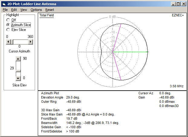
Figure 2: 33' LLA on 80m (Azimuth)
Example model plots from a 33' terminated LLA on 80m are shown in Figure 1 and
Figure 2 at right. Click to enlarge each plot image.
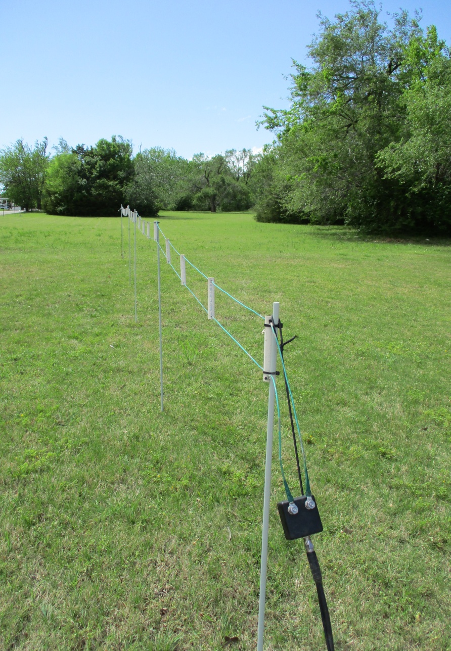
The Physical Antenna
The physical installation isn't much more complicated than the model. I used
four-foot fiberglass electric fence poles to support the ladder, and hold the spreaders
in a vertical orientation, which is important to the pattern cleanliness. I used
two small guy lines, one on each end, to pull the end poles vertical, and the wires
taut. The installation height isn't critical, but since I pushed the poles
about 6" into the ground, the top wire of the ladder was at about 3'6", or
just over one meter (1m) above the soil.
Using the computer models as a guide, I selected a length for the prototype that would
give a nice directional pattern on 160m, 80m, and 40m: just over 33' long between the
terminating resistor and the feedpoint transformer. This length was easy to
test-stand in my front yard, where I have plenty of room to work without getting close
to the permanent antennas behind the house.
Although the LLA might appear similar to beverage antennas, the LLA does not use the
ground as one of the antenna conductors, and does not require any ground connection
at or near the antenna. Neither of the antenna wires should not be connected to
the ground. The coaxial shield can be grounded near the antenna if desired, but this
is not necessary. Grounding of the coaxial shield at the building entry is always
best practice for any antenna, for lightning safety and to drain static charges.
Since the transformer provides a DC-shorted feed point for the coaxial cable, grounding
the shield at the building entry point is sufficient to completely drain static charges
from both wires.
The Electrical Antenna
The transformer is a hand-made isolated beverage transformer, wound for 75-ohm cable,
following the same W8JI design used by
DXE for their
commercial transformers.
The resistor chosen was the same 470-ohm, 2-watt, non-inductive resistor used by DXE in
their beverage transformer kit.
To verify that the antenna was wired properly, and connections good, I did an impedance
sweep of the antenna using an antenna analyzer. It showed a steady reading of
75Ω +/- ~10%, from around 1.2MHz up to above 20MHz. So the transformer,
feedlines, and termination were all working as expected.
The overall gain of the antenna is quite low, even for a receiving antenna. To
bring the signal levels up a bit, I added a
DXE RPA-1 preamplifier,
which has a gain of about 16dB. This is a bit more than offered by the preamplifiers
in most transceivers, and the resulting signal levels were just about right. The
S-meter was zero on band noise, but once the band became busy, the S-meter readings
were S9+. I placed the preamplifier next to the radio, and this was more than
sufficient; if one wanted to place an amplifier out at the antenna, this would
be fine too, and might provide a slightly better
SNR at the radio.
How Does It Play?
The prototype antenna was installed so that the center of the main lobe was pointed
due east from my location in central Oklahoma.
I started testing on 40m, so that I could make the most of available FT8 signal traffic
to get a picture of the directivity of the antenna. This is near the shortest
wavelength for which the 33' antenna will have a good main-lobe pattern.
Initial results did not disappoint.
After several hundred reception spots on 40m, the resulting distribution of received
stations showed a visible preference for stations to the east, and a weaker response
for stations to the west.
As summertime is approaching, the 80m and 160m bands are not nearly as popular now
as they are during the winter months. Even so, I was able to collect enough
80m reception spots to observe that the 33' antenna response on 80m was similar to
that seen on 40m. This further supports the patterns described by the model,
and shows that the antenna can be used unmodified on multiple bands.
Very few amateur operators have the ability to measure the
front-to-back (F/B) ratio
of their antennas, and I am no exception to this. Truly measuring F/B for
an HF antenna requires equipment, and plenty of flat, unobstructed space, due to the very long
wavelengths involved. However, since this antenna is experimental, I wanted to find a
way to systematically use the data I could collect to get an estimate for the effective
F/B I was getting on real-world signals. Models are great, but if the real installation
shows no evidence of F/B, it may not justify the trouble of building and installing that
design for most people.
I collected a few evenings' worth of FT8 spot data on 40m, and then used some scripts
and math to extract an estimate of the F/B ratio of the antenna on that band. I
used different termination resistor values on different days, to see how the model compared
to the real antenna as the termination value was changed. The calculations used were
a little involved, but the basics are roughly as follows:
- Gather data from a couple of hours before sunset to a couple of hours after sunrise;
this makes sure to cover the typical propagation cycle for both east and west directions.
- Pick the best SNR estimate for each unique callsign from the data during that time,
and exclude all other spots from that station.
- Exclude spots from transmitters within an exclusion radius, to limit NVIS influence
on the results.
- Normalize each spot to a single metric that considers both the SNR estimate and
station distance. This way, close transmitters with good SNR don't dominate the
average over distant transmitters with lower SNR estimates.
- Average the metrics from the front and back of the antenna separately; the
"front" and "back" were defined by two equally-sized arcs,
centered on the axis passing through the centerline of the azimuth repsonse of
the antenna. Spots outside these arcs were excluded.
- Use the ratio between the front and back metrics to estimate the F/B ratio based
on the observed stations, their SNR estimates, and their reported distance.
What I found was that the termination value did influence the F/B, but the value wasn't
as critical as I expected. Both the 470Ω and 680Ω terminations did
well in real-signal tests. Straying from this range causes the F/B to suffer
noticibly.
The best F/B estimate was with the 470Ω resistor, as predicted by the model.
As expected, the F/B estimate varies with propagation and stations available to receive,
but after a few nights of measurements, the value seems to be in the range of 6dB
to 10dB. When you consider that the overall F/B is estimated over many different
arrival angles, and that it is still competitive with the theoretical F/B for an ideal
two-element yagi antenna, the experiment appears to be rather successful.
This antenna is still very early in its testing, but the initial results are good
enough to warrant more testing and experimenting on other bands. Because of the
variability in the F/B estimates caused by station participation, propagation, and
all the exclusion angles used in the calculations, a better F/B estimate could be
done if many weeks or months of data were considered, instead of just a few days.
Likewise, the calculation of the per-station metric itself can be done in several
different ways, since the received SNR and distance combination can be combined in
different ways, and even together are an imperfect metric of true antenna performance
for each station.
How Does It Work?
Honestly, I don't know. ;-)
However, there are a few things I can say about the design. The antenna is
not dissimilar to other large or elongated loop antennas. Terminating such
loops opposite the feedpoint is also not a new idea. VE7CA
has experimented with antennas that are a more regular shape, but essentially the same
idea, with a loop of wire, terminated on one side, and fed on the other. If
you calculate the physical area enclosed by a 3' diamond antenna, and then compare
it to the area enclosed by 33' of 3.5"-wide ladder line, they are very similar,
so the difference between the 33' LLA and VE7CA's antenna is mostly one of geometry.
That may be one advantage of the LLA, which is that increasing the area inside
the loop is very easy, and doesn't require making the antenna any taller. The
LLA can be completely and easily hidden inside a yard with a privacy fence, with
the top wire well below the top of the fence. Regardless of how long the antenna
is made, the height of the antenna can remain below shoulder height, making it easy
to modify and maintain.
Using relays to remotely lengthen or reverse such an antenna should also be rather
simple, and the relay wiring could be run along the ground, to limit interaction
with the antenna element itself.
Copyright (C) 2021 by Matt Roberts, KK5JY.
All Rights Reserved.