The Small Vertical Loop Antenna for HF Reception

Matt Roberts - matt-at-kk5jy-dot-net

Published: 2017-01-13

Updated: 2022-07-23


Installed Antenna
My original interest in small receiving loops was focused on two-element arrays of such elements, used to form a phased array for improved receive performance on the HF bands.  The individual elements of that antenna design were simple wire loops, very small compared to the wavelengths to be received, and not resonated nor tuned for any of the bands where it is used.  Such arrays can compete with enormous Beverage antennas many times their size.  However, even a single wire loop of this type can be a very effective HF receive antenna for long wavelengths, offering a substantial advantage over many types of transmitting antennas for HF reception.  As such, it deserves some additional discussion of its own.

The lossy, untuned, electrically-small antenna, whether a vertical, loop, or horizontal dipole, turns out to be an excellent transducer for HF skywaves.  The efficiency of such an antenna is very low, sometimes on the order of dozens of dB below an isotropic antenna.  However, it turns out that the low efficiency actually helps to improve the overall signal-to-noise ratio of received signals.  The reasons for this are best discussed in another article, but it should suffice to say that HF operators have known about the desirable properties of lossy receieve antennas since the earliest days of radio, and the Beverage antenna is but one example of a family of antennas that exploit low efficiency to improve the SNR of skywave signals.

A small, vertical, untuned (nonresonant at the desired reception frequency) loop antenna is essentially a compact vertically-polarized antenna that is self-contained, and does not require radials or counterpoise. The loop can be placed in relatively close proximity to the ground, although its overall pattern shape is similar to what you might expect from a dipole that is raised to nearly λ/2 above the ground.  The ground dependence of a vertical loop element is very low, with the main effect of the ground being its influence on far-field gain (efficiency).  Since we will assume the efficiency of the antenna element to be already low, given its small size with respect to wavelength, this effect on efficiency is not critical to the antenna.

For the purposes of this article, I will refer to such an untuned electrically-small loop antenna, used only for receive, as a "small receiving loop," or SRL.  There are a number of antenna types that could be considered to be a small receiving loop, but herein I am referring only to those loops that meet the description above.

Far-field patterns for the 40m, 80m, and 160m bands for a SRL are shown in Figure 1 through Figure 9.  The loop being modeled is diamond-shaped, 30in (2.5ft) per side, and fed at the bottom corner.  The loop base is approximately five feet (5') above ground, which places its top corner at about eight feet (8') above ground.  An example of such a loop is shown in Figure 10.  Click on each figure to enlarge.


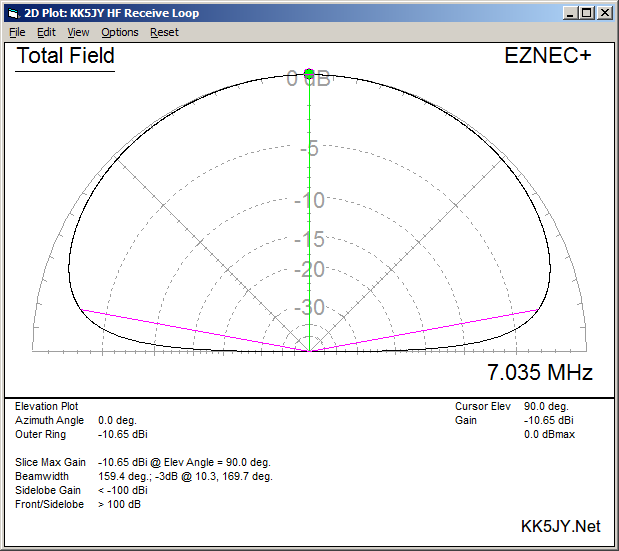
Figure 1: 40m Elevation Pattern
(Peak Elevation)

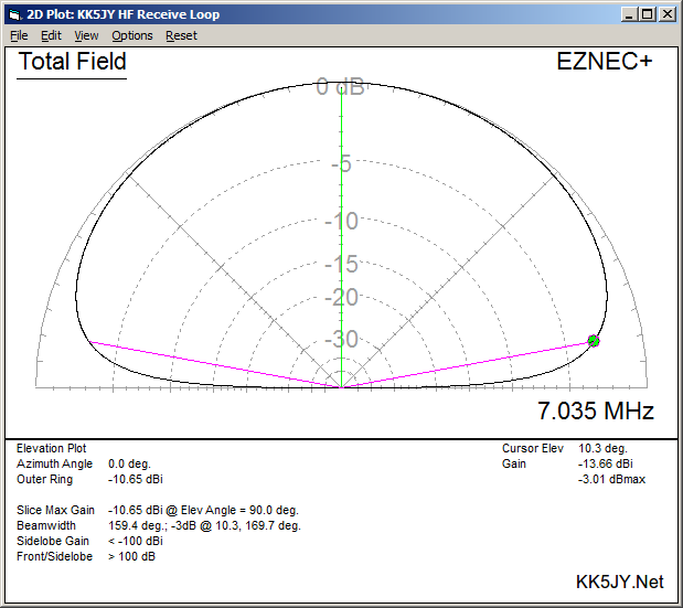
Figure 2: 40m Elevation Pattern
(-3dB Elevation)

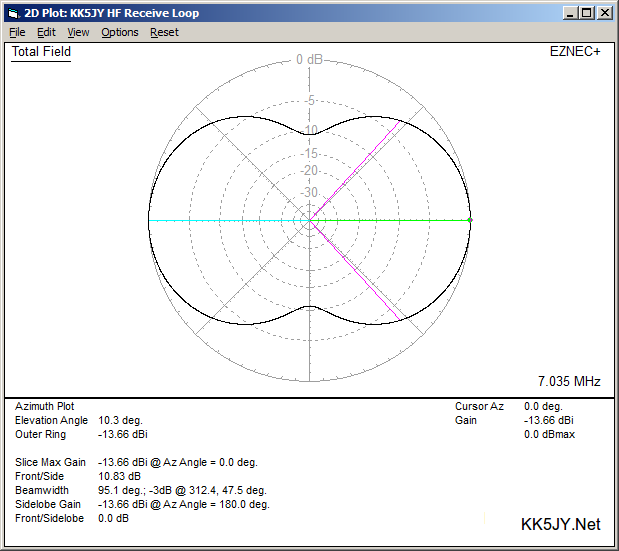
Figure 3: 40m Azimuth Pattern
(-3dB Elevation)
 

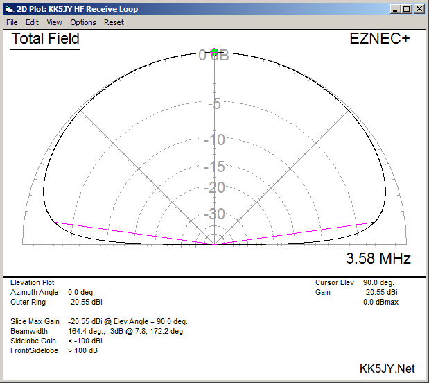
Figure 4: 80m Elevation Pattern
(Peak Elevation)

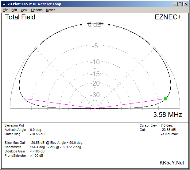
Figure 5: 80m Elevation Pattern
(-3dB Elevation)

Figure 6: 80m Azimuth Pattern
(-3dB Elevation)
 

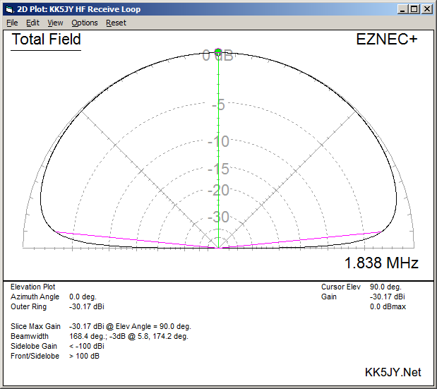
Figure 7: 160m Elevation Pattern
(Peak Elevation)

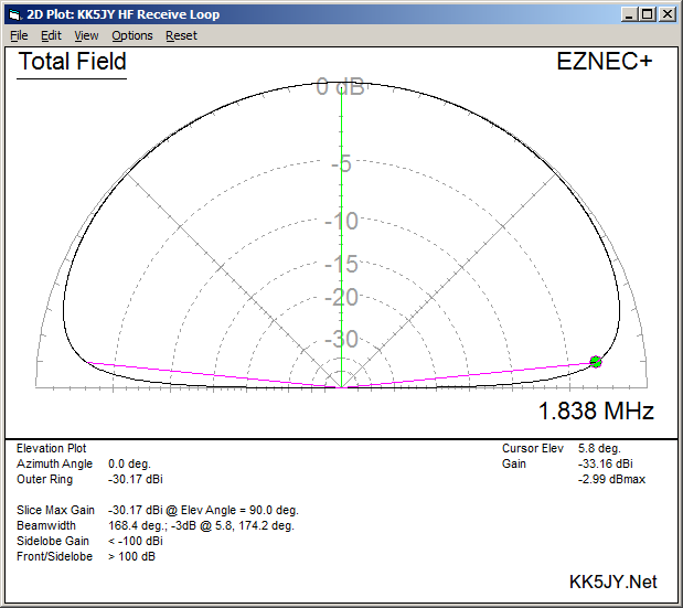
Figure 8: 160m Elevation Pattern
(-3dB Elevation)

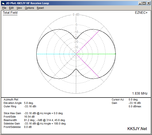
Figure 9: 160m Azimuth Pattern
(-3dB Elevation)
 
Loop Element
Figure 10: Loop Element
Loops are "balanced" antennas, and when fed from coaxial cable, they require careful decoupling from the outer conductor surface of the feedline.  The SRL shown in Figure 10 is directly-driven, using a coaxial feedline choke at the feedpoint to prevent RF pickup from the coax shield.  I later replaced the choke with a DC-isolated Beverage antenna transformer (Figure 11), like those used by W8JI for his Beverage antennas.  This is the same type of transformer I used on the loop-on-ground design, and it is the same design used by DXE for their commercial version of W8JI's device.  The Beverage transformer did a much better job of preserving the loop's rather sharp nulls—and over a broader range of frequencies—than the choke.  The transformer DC-isolates the antenna element from the feedline, and provides a DC-shorted feedpoint, which is nice for preventing any static build-up.

Loop Element
Figure 11: Hand-made
Isolation Transformer

At first glance, the elevation patterns appear unremarkable; in fact, they are somewhat similar to the "cloud warmer" pattern of a low dipole antenna.  The azimuth plot also seems to support that assessment.  However, if you look closely at the shape and supporting data on each plot, you will see that these are not typical NVIS patterns.  In fact, the -3dB elevation angles for the 40m, 80m, and 160m bands are 10.3°, 7.8°, and 5.8°, respectively.  These are not NVIS angles -- these are DX angles.

What does that mean in real life?  It means that the SRL is able to receive skywave signals with consistent gain at nearly all arrival angles.  Its low-angle response is better than most vertical monopole antennas, making it a very capable DX antenna.  However, because the high-angle pattern is also intact, the antenna can also hear NVIS signals with very similar gain figures.  This makes the antenna an all-purpose device for reception.  Most antennas are either good at high- or low-angle reception, but not both.  Those that can hear low-angle skywaves have enormous gain differences between the low angles and the higher angles above them.  This means that DX signals appear at the receiver with far less energy than the higher-angle domestic signals, making it sometimes difficult to "dig out" the DX signals from the much stronger domestic stations surrounding them.  The more even gain distribution of the SRL tends to equalize the SNR of received signals, to present them at the receiver at a more consistent strength.

But that's not all.  The azimuth pattern of the SRL has two nulls in it, much like a dipole antenna.  And like a dipole antenna, these nulls emit from the "sides" of the antenna.  However, a dipole with this low-level pattern would have to be very high, between λ and λ/2 above the ground.  That places the center axis of the dipole's nulls also very high in the air.  In contrast, the SRL's null axis is close to the ground level, where it can do the most good rejecting local QRM.  The high dipole will be quite "good" at hearing QRM at negative angles off its ends, such as from a neighboring house, while the SRL has a better chance of nulling out such signals.

Where the small receive loop really shines is in S/N optimization for skywave signals.  Even in an interference-free environment (if such a place exists), the high-loss nature of the untuned small receiving loop allows it to hear autocorrelated signals better than it hears the random noise around those signals.  Users of short untuned vertical antennas have reported similar effects when they deliberately load their vertical antennas with resistive loss.  The result is that listening to signals on a small vertical loop can yield a better signal-to-noise ratio for the signals we care about (CW, SSB, RTTY, PSK, etc.).

Panadapter 40m CW
Figure 12: Panadapter on 40m CW

Panadapter 40m FT8
Figure 13: Panadapter on 40m FT8

40m DX Map
Figure 14: 40m Coverage (12 Hours)
Figure 12 shows a sample of the performance of the SRL while used on the 40m CW band during a particularly busy evening.  The antenna was indoors, close to numerous electronic devices, and still provided an excellent SNR and low noise floor.  Compared to the other antennas I had available at the time for 40m, the SRL's SNR performance was by far the best.  While there is nothing "magical" about this antenna, the SNR improvement alone tends to cause signals to naturally lift out of the noise.

In late 2018, I did some extensive experiments with FT8 and this antenna.  I moved the antenna into an open area of my yard, and turned it to null out some interference from what I suspect is a noisy light ballast in a neighbor's house.  Using a 33' vertical antenna for transmitting, and the SRL for receiving, I was able to make around 4,000 contacts in just over a month's time, across the 15m, 17m, 20m, 30m, 40m, 80m, and 160m bands.  The antenna produced excellent signal levels using only the 10dB preamplifier built into my TS-590SG.  I had intended to add a mast-mounted preamplifier, but I still haven't gotten around to it, because it hasn't yet been needed.  Figure 13 shows a sample of WSJT-X running FT8 on 40m with the SRL attached.  Figure 14 shows a typical coverage map using the SRL over approximately twelve hours.

Using a single loop element has definite advantages over a two-element array.  First, it allows simultaneous reception from opposing azimuth angles.  Here in the central US, most amateur signals tend to arrive from the east and from the west.  A single SRL element will hear both NVIS and DX signals from both the east and west simultanously.  This provides wide geographic coverage from a single antenna, while simultaneously improving S/N ratio and providing two nearly horizontal nulls that can be rotated to remove a specific interference source that might be closeby.

The performance of a single SRL approximates an unterminated Beverage antenna many times its size, while providing the extra advantage of being rotatable.  In contrast, the two-element array approximates the performance of a terminated Beverage antenna, which is largely unidirectional.

There are uses for both the a single-element SRL and the two-element phased array version.  While the two-element array provides the extra directivity that many people seek from a receive antenna, the single-element loop still has plenty of advantage over most transmit antenna types, such as a full-sized vertical.  My own location is almost unusable on 160m when using a vertical antenna for both transmit and receive.  However, when using dedicated receive antennas, 160m comes alive with signals during major operating events.  The usefulness of simple receive antennas such as this should not be underestimated.

There is nothing special about the 30" square that I used for my prototypes.  I chose a size that was electrically small for the wavelengths where I wanted to operate, and also a size that was easy to measure, construct, and carry.  A smaller SRL will generate lower signal levels, but it will provide deeper nulls to the sides.  A larger SRL will generate more signal, but have less attenuation in the nulls.  The size can thus be chosen to balance the needed signal level with the directivity desired.  I prefer to have enough signal to "set the noise" in my receiver when I connect the antenna.  If one prefers an antenna that has very deep nulls, and is willing to add a preamplifier, a much smaller loop can be designed that will provide similar signal levels at the receiver.  If a preamplifier is used, a model with the lowest practical noise figure should be selected.

Combination devices, consisting of an SRL and a broadband, mast-mounted preamplifier are readily avaiable from a number of manufacturers.  Unfortunately, most such devices are quite expensive, and as a result, the SRL design doesn't receive the attention it deserves.  I found that by properly sizing the loop element, and using quality low-loss coaxial cable, I could forego the preamplifier, or use the preamplifier built into the radio, thus eliminating the bulk of the cost of a quality commercial SRL.  This makes the loop much less expensive to construct, and it also removes a common point of failure, since a mast-mounted preamplifier is prone to failure due to static, nearby lightning strikes, temperature extremes, and other such environmental abuse.

Strictly speaking, a receiving loop need not be an ideal shape or size.  While a symmetric loop will produce the most predictable and reliable nulls, nearly any loop of wire can be used as an SRL.  The porch loop is an example of a second SRL built to experiment with a loop that is less-than ideal in nearly all respects — including size, shape, location, height, etc.  That antenna quickly became my primary HF reception antenna for longer wavelengths, daily capturing dozens of DX countries on multiple continents on 20m, 30m, and 40m.

If materials are carefully selected and assembled, a single-element quality SRL can be built for only a few dollars, including the isolation transformer, and have performance every bit as good as its $500 commercial brethren.  By using quality coaxial cable, such as flooded F6 cable TV coax, losses can be kept very minimal, eliminating the need for a preamplifier.  Such cable is widely available, and very inexpensive, because the cable and satellite industry uses tons of the stuff for customer installations, so it is widely mass-produced.  Remember, if the receiver noise level goes up when attaching any receive antenna, the antenna system as a whole is generating more than enough signal to drive the receiver, and a preamplifier is not needed anywhere in the signal path.  Constructing a loop that can generate sufficient signal levels, and then combining that with low-loss cable to preserve that signal all the way to the receiver, will provide superior performance to any antenna with a mast-mounted preamplifier, because the preamplifier itself will raise the noise floor, canceling some of the SNR improvement that the antenna is supposed to provide.

When I started tinkering with this antenna, I had just about given up on HF radio, because of the constant fight with RFI and the uneven noise floor that I would often see due to all of the electronics and power lines that surround me.  I don't have room for Beverage antennas, and even a shortened Beverage would have to extend nearly up to the walls of the neighbors' houses.  I built the first small vertical loop on a whim, just to see what it might be able to hear, and was shocked to discover that it was not only not deaf, but it could hear better than my full-sized antennas.  The signal levels are lower, but the SNR is much better.  Since that time, I have spent most of my ham radio time experimenting with non-Beverage receive antennas.  This project led me to experiment with another very effective receive antenna design, the loop-on-ground antenna, which I have used successfully on bands from 160m to 20m.  The experimentation continues, but I am finding that everything I thought I knew about antennas goes out the window when trying to receive HF skywaves, especially on the longer wavelengths.  The ability of a small piece of wire, when properly sited and constructed, to improve the reception of HF skywaves continues to amaze me.  Needless to say that I would not still be on HF without such antennas.


Copyright (C) 2017-2022 by Matt Roberts, All Rights Reserved.