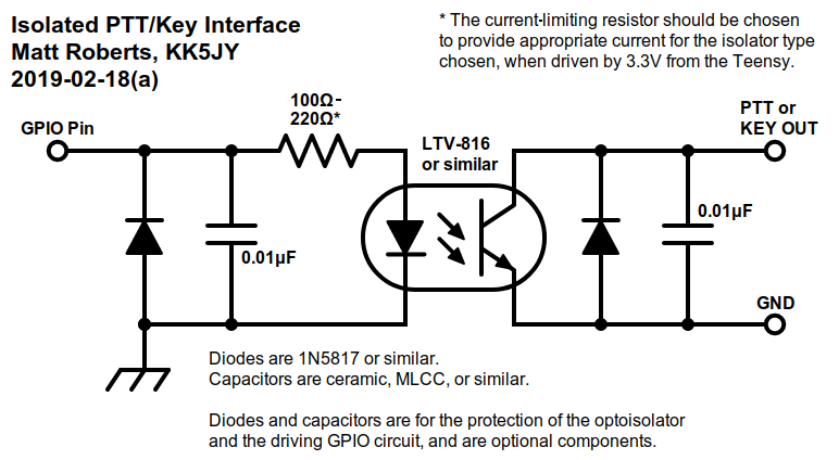
AnyRig Interface - Version 1.0

Matt Roberts - matt-at-kk5jy-dot-net

Published: 2019-02-17

Updated: 2019-04-18


AnyRig Prototype


Figure 1: Prototype Block
Diagram


Figure 2: Output Module
Flow Diagram


Figure 3: MOSFET PTT/Key
Interface Circuit


Figure 4: Optoisolated
PTT/Key Interface


Figure 5: Transmit
Audio Isolator


Figure 6: Receive
Audio Isolator


Figure 7: Teensy 3.2
Default Connections


Figure 8: Teensy Audio
Default Connections


Figure 9: Hardware
Audio Level Control


Figure 10: Prototype Detail
(Left)


Figure 11: Prototype Detail
(Right)


In Search of a Better Digimode Interface

Amateur radio operation is increasingly about digital modes.  From digital voice to conversational and experimental data modes, setting up a modern station will eventually mean tying one's PC, tablet, or smart phone to an HF or VHF+ transceiver.  Unlike most consumer audio devices, interfacing a computer to a radio transceiver involves more than just raw audio.  The connection involves bidirectional audio, transmit/receive (T/R) control, and sometimes hardware keying for CW or RTTY operation.  It may also be necessary to electrically isolate the connections between the PC and radio, to prevent RFI.

Many newer radios provide some of these functions via USB or serial connection to the PC.  It is still often desirable to use an external interface device for any number of reasons:
Electrical isolation between the radio and computer.
Residental amateur installations often have to contend with ground loops, EMI caused by strong RF fields, etc.  Isolating the radio transmitter from the computer driving it can often solve or minimize such issues.
Provide more functionality than offered by the radio's USB port.
Some radio models don't support VOX operation on their line input port, meaning that digimode tones can't operate the VOX circuit.  Very few radios support RTS/DTR or audio-driven keying of PTT, FSK, or CW—the most widely-supported methods across digimode software packages—without external interface hardware.
Provide more stable functionality than that offered by the radio.
Many digital mode software packages have limited (or no) support for newer radios, and the support that exists is sometimes buggy.  Even open-source libraries for radio control are often out-of-date by the time they make it into operating systems and software releases.  Using a dedicated hardware interface to control keying and audio can be an easy way to get a solid, reliable control of any radio from any computer.
One popular radio interface is the SignaLink.  The idea behind the SignaLink is that the computer or mobile device only needs to know how to drive a generic AC97 USB sound device.  The SignaLink handles the transition to analog audio, the T/R control, and the DC isolation between the radio and the computer.

Other interfaces have been developed for more precise control of CW and FSK transmitters.  For example, the Fldigi software supports using the audio from the right channel of a stereo sound device to provide tightly-timed keying pulses.  It does this by emitting a high-frequency, high-duty-cycle tone on the right channel, which then drives a simple conversion circuit, providing an open-collector output for PTT, FSK or CW keying.

Hardware developed for the "maker" movement in recent years provides some nice building blocks for those who enjoy building simple gadgets for their station.  I recently found myself in need of a SignaLink-like device, but unwilling to drop $140+ to get one, especially on short notice.  What I discovered was that I already had all the hardware on hand to make an equivalent device, with more options and features, a better audio codec, and best yet, much less expensive—weighing in at just under $50.  With a bit of firmware work, and a few external components, I was able to make it exactly what I wanted.

The device is described below as a "software kit," with schematics for simple circuits and the firmware needed to bring it all together.  A complete hardware prototype is also described, with the various components assembled into small modules.  The kit provides the same key features of the SignaLink, but with a number of improvements:
More options.
Nearly everything can be adjusted to best suit the needs of the specific radio, software packages, and modes desired.  The current firmware supports any combination of a number of features, using a single USB connection to the host computer:
Better codec.
The SignaLink is well-known for having noise issues, mostly self-inflicted.  This kit uses a codec board that is designed for high-fidelity audio, making it perfect for weak-signal digital modes.  The codec in the prototype shows a no-input noise floor of around -75dB of full-scale, RMS.
Fast, Quiet Operation.
By using solid-state switching devices, relay noise can be eliminated, even for high keying voltages.  While using a relay is still an option, the firmware supports virtually any switching device, including MOSFETs, BJTs, optoisolators, and solid-state relays.
Hobbyist friendly.
All of the hardware used is widely-available in hobbyist circles, and well-documented.  Unlike the high-density SMD construction of other devices, this design is very modular, and the construction of the few needed interface circuits can be done with through-hole components, easily assembled by anyone with entry-level soldering skills.  The use of through-hole components also makes it easy to breadboard a device for testing and experimentation.
Less expensive.
By using low-cost core components, and providing the flexibility to choose only the interface hardware one needs, the cost of the device can be kept to a minimum.  For example, some people might prefer complete transformer-based isolation, with a pair of high-voltage optoisolators for T/R switching and CW/FSK keying.  Others might be able to directly connect the audio lines to the radio, and use a single small-signal MOSFET for T/R control.  By choosing only the options one needs, the best device for the lowest cost can be obtained.
Open source.
The firmware is completely OSS, which allows anyone to customize any part of the operation of the device, add features, etc.

Kit Description

The interface hardware is based around two hobbyist boards made by PJRC.  One is the Teensy microcontroller, and the other is the matching audio adapter, which adds a high-fidelity sound device to the Teensy, with headphone, microphone, and line-level audio connections.

The Teensy can emulate a number of USB devices when connected to a PC, including a sound card, a serial port, a MIDI device, or combinations of these devices.  In this kit, the microcontroller will use the audio adapter to provide analog audio to/from the radio, while appearing as a USB sound card to the host PC.  While the digital audio stream is passing through the microcontroller, the firmware will watch that stream, using the audio levels to control PTT or keying devices.

The audio adapter is a stereo device, in both directions.  Within the firmware, each the playback channels can be attached to its own output module, which is a software object that controls hardware keying and timing.  There are two module types included in the firmware: a VOX module, and a Key module.

The VOX module is useful for most general digital modes, providing a typical VOX-style PTT control, with adjustable hang-time. This is the type of operation familiar to users of the SignaLink.

The Key module is similar to the VOX module, but has specialized timing for driving the keying inputs of a CW or FSK transmitter.  The switching time on both the rising and falling edges of each audio envelope are treated with equal delay, so that the width of each audio pulse and space are preserved and converted to precise hardware key closures.

Each output module is very simple, and a generic flow diagram is shown in Figure 2.  The playback audio is read digitally within the Teensy CPU on its way to the sound device, and the levels are measured.  This is used to drive T/R or keying logic, which in turn, controls a GPIO output pin on the Teensy.  The timing of the GPIO pin transitions depends on which module type is attached, and how it is configured.

In addition to using audio as a trigger, either module can optionally use an RTS or DTR state from the Teensy's USB serial port to drive the switching logic.  The trigger can be in addition to, or even instead of, the audio-driven triggers.  Since many digimode software packages support using a serial port's handshaking lines to control a radio, the firmware supports passing these signals through to the output modules.  The combination of audio and handshake line keying provides for any number of keying configurations, over the same USB cable.

The GPIO output from each module can be used to drive a switching circuit.  A simple example is the inexpensive MOSFET circuit shown in Figure 3, which provides an open-drain output compatible with the vast majority of transceivers on the market.  Many radios already have isolated or properly-grounded signal paths for digital mode I/O, and for such radios, this MOSFET circuit is the only custom circuit that needs to be built to complete the kit.  Alternatively, an optoisolator can be used, which can be sized for whatever voltage tolerance or ground isolation that is needed.  An example of such a circuit is shown in Figure 4.

Some common output module configurations are shown below:

LeftRightNotes
VOXThis is the simplest configuration, most closely resembling the SignaLink device.  The audio of the left channel will activate the VOX logic for PTT control, requiring only a single output switch circuit.
VOXKeyThe left channel operates identically to the above case, but the right channel is used to drive an independent keying device.  This keying device uses much faster timing, and symmetric debouncing, in order to be useful for either CW or RTTY hardware keying of a transmitter.
PTTAnother useful configuration skips VOX altogether, and instead the T/R function is performed explicitly by providing a continuous tone on the right channel.  Fldigi is one example of software that can provide PTT control in this manner.  The modem audio in this configuration is provided by the left channel only.
PTTKeyFor applications where transmit audio isn't required at all, the device can control a combination of CW, RTTY, and PTT keying hardware.  Such a configuration is ideal, for example, with semi-QSK CW or RTTY operation, where one channel controls T/R with better precision than a VOX module, while the other channel controls the actual CW or FSK keying, and no output audio is required.
KeyKeyAnother possibility for radios with a USB port for CAT and audio is a microcontroller-driven version of the keying interface for CW and/or FSK.  When configured with a Key output module on each channel, the device can be used as a hardware keyer for CW and RTTY, when used with software like fldigi.  The CW keying could be provided by one channel, and the FSK keying on the other.

Each Key output module should be configured with the pin number to which the keying circuit is connected.  Each VOX module should also be configured with an output pin number, and can also be configured with an A/D input pin number, to which a potentiometer can be attached, to provide for variable delay control of the VOX hang time.  The VOX module can alternatively be configured with a fixed hang time, if desired.

Each module type also supports an optional second output, intended to drive an indicator LED.  This is for configurations where the main output is driving a current device, such as an optoisolator, or a BJT, so that each output module can have a dedicated LED indicator, while ensuring that the per-pin current limits of the CPU are not exceeded.

Regardless of the module(s) configured, the analog audio still appears at the line and headphone level outputs of the audio device.  The configuration of output modules just determines what extra actions will be performed based on the audio levels present.  Receive audio from the radio is captured by the audio adaptor just as with any other sound card.

If DC isolation of the audio pathways between the radio and interface is desired, simple isolation transformer circuits, such as those shown in Figure 5 and Figure 6 can be combined with optoisolated keying circuit(s) to provide complete electrical isolation.

While most new radios have adjustments for setting transmit and receive audio levels, and many newer software packages have similar controls in their user interfaces, it may still be desirable to add hardware level controls to the transmit and/or receive audio paths.  This is a very simple addition, and can be wired as shown in Figure 9.  Such a control can be placed on either side of an isolation transformer, or instead of a transformer.  The audio codec can also be configured to use custom gain levels, select LINE or MIC inputs, etc., as a further method of controlling audio levels.

Since the Teensy can emulate a full USB serial device, the firmware also supports serial pass-through, to allow CAT control (or control of any other serial device) from the same interface.  The only additional hardware required to use this feature is a level shifter IC, to convert the 0V to 3.3V output of the Teensy's GPIO pins to the bipolar RS-232 voltages, or to CI-V levels for Icom radios.


A Working Example

For my own use, I chose to start with a prototype with several options: This configuration gives me the ability to run any of the modes that I could have run with a SignaLink.  It also allows me to use full- or semi-QSK for CW, and hard-keyed RTTY.  For these modes, the AFSK output drives the VOX module for PTT control, while the right-channel keying options in Fldigi control the hard-keyed data.  The example connections for Teensy 3.2 are shown in Figure 7.  The example Teensy audio connections are shown in Figure 8.

A block diagram of the prototype hardware is shown in Figure 1.

Views of of the prototype boards with most interconnecting wires removed are shown in Figure 10 and Figure 11.  These views make the key components of the prototype easily visible.  Instead of building all of the components onto a single board, I chose to build several smaller boards, each built with specific functions.  This was done to allow me to easily add or swap components for testing of the prototype.  This design could also be assembled on a single, compact prototyping board.


Hardware Selection

The main hardware components used in the prototype are commonly available, and described below.
Teensy
The Teensy "stack" was constructed from the following three components, available from SparkFun: The audio board was placed on bottom, and its header pins were trimmed to allow it to be placed flat on a mounting surface.  The headers on the Teensy 3.2 itself were left full-length to allow it to be "docked" on top of the audio board.  The other connectors in the header kits were not used, since they get in the way of connecting the two boards.

I added two capacitors across the pads shown on the bottom image in Figure 7, to prevent ripple and other power fluctuations in the +5V from the USB cable from adding noise to the audio channels.  The values I used were 10μF || 0.1μF.  The two larger pads indicated are connected directly to the USB power pins in the micro USB connector, and are located on the bottom of the Teensy board.

Caution:  The audio board uses a floating ground connection on the headphone jack.  There is even a caution printed on the bottom of the PCB, next to the headphone output pads, noting that the headphone VGND should not be connected to the GND pins anywhere else on the audio adapter or Teensy CPU board.  If the headphone output is used to drive a transmitter, the audio signal should be routed through an appropriate audio isolation transformer, between the headphone jack and the radio's audio input.
Boards
I used a number of small boards for building the prototype.  These are so-called "solderable breadboards" whose layouts match common breadboard sizes.  Sparkfun sells boards of the size I used, available here.  I chose several small boards, rather than a single larger one, in order to make it easy to add or remove modules from the kit, for experimentation purposes.

Larger boards, able to accommodate all of the components of a typical configuration are available from AdaFruit and from SparkFun.  The type and size of board to use will largely depend on how many external components are selected.  E.g., a board with two isolation transformers and optoisolators will require significantly more board space than a single switching FET.
Audio Isolation
I used the Xicon 42TL016-RC for line-level audio isolation.  This transformer is rated for 300Hz to 3400Hz, and is available for around $2 each at Mouser.  Most "box" radios are band-limited to roughly 300Hz to 3000Hz, and are a good match for this part number.  For use with newer radios—especially those based on SDR technology—with a wider frequency range available when operating in SSB mode, it might be worth finding a transformer that has more bandwidth.  There are other parts that have a wider frequency range, but they tend to be quite a bit pricer, too.
Isolated Switches
There are all kinds of optocouplers that can be used to provide DC isolation of PTT, CW, and FSK hardware inputs from the interface.  The ones used in the prototype were LTV-816 by LiteOn, mostly because they were the parts I already had in my collection.  That said, it's actually a good choice for this purpose.  The maximum voltage from collector to emitter is around 80V, allowing it to switch just about any solid-state radio around, and quite a few tube-based designs.  Physically, the 816 is available in a DIP-4 package, and they are thin enough to sit side-by-side in a larger DIP socket.  I fit two together in a DIP-8 socket.  The larger 826 is basically two 816 parts in a single DIP-8, making an 826 physically and pin-compatible with two 816 parts.

The LTV-816 has an internal LED that can sink up to 50mA—much higher than the per-pin GPIO current limits of the Teensy board.  However, the CTR and VCE saturation curves in the datasheet indicate that the phototransistor should have low "on" resistance with LED drive currents as low as 10mA.  I tried LED current limiting resistors in the range of 100Ω to 220Ω, all of which resulted in a very small voltage drop across the phototransistor in its "on" state, and driving my TS-590SG with no issues.  Given the Teensy's preference for 10mA maximum per GPIO pin, 220Ω is probably a safer value, requiring only about 9mA of LED current.

At least one person has reported to me that certain older equipment may require more current than modern rigs in order to reliably operate the PTT circuit.  Optical devices with much higher CTR are also readily available, including the FOD-819 by On Semi, and any number of photodarlington devices, such as the LTV-815 by LiteOn.  There are even some MOSFET-based isolators available, but do pay careful attention to the 3.3V output limit of the Teensy, as well as its 9mA-per-pin current limit.
MOSFET Switches
If DC isolation of keying contacts is not required, simpler circuits can be constructed from inexpensive MOSFETs.  I like the BS170 or 2N7000 n-channel enhancement-mode small-signal MOSFETs for this purpose.  With 3.3V of gate drive, these parts can pass up to 250mA of keying current—more than enough for any solid-state radio.  These devices can typically switch up to 60V, and they have a low RDS(ON)—especially the BS170.  Since gate current is negligible in a MOSFET, it should be possible to connect both a MOSFET and an LED to the same GPIO pin, without exceeding the 10mA recommended per-pin current limit of the Teensy.  This can simplify configuration and board layout, and can also free up CPU pins for other uses.

Note that most of the GPIO pins on the Teensy are in high-impedance state when the device is started or restarted.  The BS170's gate and any bypass capacitors connected to it can easily retain enough charge to keep the transistor turned on while the GPIO pin is in high-Z state.  As a result, the high-value pull-down resistor shown in Figure 3, connected between the MOSFET gate and source, is highly recommended.

The BS170 and the 2N7000 are both available from Mouser, for around $0.40 each in small quantities.
GPIO Protection
GPIO and switching components in the prototype are protected using a combination of diodes (to protect against reverse polarity) and nonpolar ceramic capacitors (to protect against RFI).  The diodes are 1N5817, which is a commmon and inexpensive high-speed Schottky diode with very fast switching time, and low VF.

The diodes are optional components, and mainly provided to guard the other solid state parts against wiring errors while building and testing the device.  The capacitors are also optional, but highly recommended.  Since digimode interface devices tend to operate in areas of elevated RF field strength, the capacitors are very helpful for bypassing RF around solid-state components, thus abating or preventing RFI issues.
Serial Interface
The GPIO pins on the Teensy both produce and consume 0V to 3.3V signals.  This includes the built-in UART devices, which share pins with the GPIO functions.  In order to support RS-232, which uses bipolar voltages of up to +/- 15V, a level converter is needed.  One of the more popular devices for this task is the MAX3232, which uses internal charge pumps to convert RS-232 to TTL-level voltages.  There is even a breakout board available from SparkFun, which has the IC and all of the needed capacitors installed on a small PCB with solder pads for 0.1" header pins.  I used this board with a DB-9M connector to add serial support to the prototype.  In order to produce 3.3V-tolerant signals, the 3232 IC should be powered by the 3.3V pin of the Teensy, or another 3.3V voltage source.
Indicators
The prototype uses common diffused 5mm LEDs for indication, taken from this kit.  The different colors have different VF, so to equalize the brightness between them, several dropping resistor values were used: Note that the Teensy 3.2 will output 3.3V on GPIO pins.  In order to estimate the proper dropping resistor value for a given LED, both for optoisolators or for visible LEDs, see this thread at PJRC.
Connectors
The choice of connectors is very dependent upon the radio used.  The prototype used 1/8" headphone connectors, with one function on each connector (e.g., transmit audio, PTT, receive audio, etc.).  A custom cable was used to adapt these connectors to one appropriate for the radio.  This configuration was intended to allow me to easily connect different hardware options for testing and prototyping.  Much simpler (and cheaper) cabling and connector designs can be used, depending on the radio.  Modular connectors are very inexpensive, and can easily accomodate enough conductors for digimode operation.

Configuration

Configuration and customization of the firmware is done in the source files, available for download, below.

The main documentation for configuring the firmware is found in the source itself.  Each block of configuration options is documented near the top of each file, starting with the main sketch file, called AnyRig-v1.ino.  Each file that has user-modifiable settings will have a section marked BEGIN CONFIGURATION.  Major components are configured in their own files, and these are described within the main sketch (INO) file.

The code files are arranged with settings and documentation near the top of the files, so that programming skills are not needed to configure the firmware.  The files can be opened in the Arduino environment, or any simple text editor, and each setting and option is described and explained in blocks of comments.

Once the desired settings have been configured, the firmware can be uploaded to the Teensy board using the standard Arduino software, and the Teensy add-on. This project is mainly a software kit, with most of the configuration done in the source files, rather than having to modify hardware to change the device behavior.


More Possibilities ...otherwise known as my short list of new features to add...

The prototype uses a Teensy 3.2, which has much more CPU power than is needed to drive some simple VOX circuits.  The Teensy LC should also have more than enough power to run the firmware, while saving a few more dollars over the 3.2.

The reason for choosing the 3.2 is that it leaves some extra power for other features in the future.  For example, instead of simply passing the audio straight through between radio and USB port, it would be simple to add any number of DSP functions into the audio stream, including: An even more interesting possibility might be more complex keying interfaces.  For example, it should be possible to convert MFSK signals into hardware keying signals for modulating simple kit transmitters that accept hardware FSK inputs.

The firmware doesn't offer such things right now, but having a DSP-enabled CPU in the device means that they are possible in the future.  There are even more powerful devices than the 3.2, if more connections or computation power is needed.  The Teensy 3.5 and Teensy 3.6 provide more CPU power and I/O options than the 3.2.


Downloads

The firmware is available in source form, below.  Installation requires the Arduino software, and also the Teensyduino add-on to add support for the Teensy boards to the Arduino environment.

All software and firmware is released under the terms of the GPL version 3.  This keeps the products freely available to end-users, but also ensures that people who use this code in their own projects will re-release their improvements to the public.  This way, the amateur radio community will have access to any improvements that might go into any commercial product based on the software or firmware.

AnyRig 1.0 Downloads  (Click Here)

Click the link above to download firmware or software packages.  The source is being released under the GPL version 3, which is also available on the download page.

Note to Integrators: If you intend to use any portion of the source code in your own project, please make sure you are familiar with the terms of the GPL3 before you publish or release your product to the public.


Release History

2019-04-07 - Add serial pass-through support.
2019-02-18 - Small bugfix to setup code.
2019-02-17 - Initial article and firmware release.

Links

Teensy - Open-source microcontroller and embedded development tools.
SparkFun - Supplier for Arduino boards and hardware.
AdaFruit - Another good source for Arduino hardware.
SignaLink - VOX-based automatic radio interface.

Copyright (C) 2019 by Matt Roberts, All Rights Reserved.