Phased Pairs of Antennas for HF Reception
Matt Roberts - matt-at-kk5jy-dot-net
Published: 2023-02-10
One question I frequently receive is how to build a phased-array
from a pair of receiving antennas. I have talked about such
antenna pairs in various articles, including the
loop-on-ground
and
phased vertical SRL articles. Using a pair of
identical receiving antenna elements, with a carefully selected
phase delay between them, allows for creation of interesting
antenna patterns, such as the cardioid. Such patterns enable
the antenna to attenuate stations or noise from undesired arrival
directions.
I will admit that I have limited experience with phased
pairs. My location is such that DX arrives from all directions,
and sometimes from multiple directions at once, so unidirectional
antennas aren't as helpful as I would like. Nonetheless, I
hear from many people who would like to try these antennas,
so here are my notes on how to pursue building
HF phased pair receiving arrays.
Try a Single Element First
If you want to build a pair of receiving antennas — especially
if your goal is to get rid of some local noise source — try a
single antenna first. E.g., if you are thinking of building
an SRL or a LoG pair, use
a single SRL or LoG at your location for a few weeks to see if that
antenna type is compatible with your gear and your location.
Any antenna type that will help your reception in a phased pair
will also give you at least some improvement as a single element
antenna, and for a tiny fraction of the price (and space).
For many people, that smaller improvement may be enough by itself.
Most of the time, it has been for me.
Some elements, such as the SRL, have some
really nice patterns already. The SRL has two nulls that can
be easily turned to point at a nearby noise source. That alone
might cancel out your QRM problem, and get you on the air for just
a few dollars.
If you choose an antenna element that doesn't like your location,
e.g., because it couples to some nearby noisy device more than your
transmit antenna, building two of an ineffective antenna will
likely perform no better. Adding pricey phasing hardware will
leave you even more frustrated.
Some well-meaning pocket-protector types will tell you that "pattern
is everything." Pattern is important, but in the real
world, you will find that some basic receiving antenna types just
work better than others in your local environment. The
antennas that work best for me are entirely different from the ones
that work for my HF contesting friend across town. The location
and what's around it make a lot of difference.
This is probably the best advice of this entire article — if
you are considering a receiving antenna pair, try a simple, single
element first, to see how it plays.
Initial References
If you want to experiment with phased arrays, even just a pair of
antennas, you're going to need to do some reading on the subject.
I suggest starting with the
ARRL Antenna Book.
The most recent version I have is the 23rd Edition from 2015.
In that edition, Chapter 6 contains information about how to
generate predictable phase delays in both receiving and transmitting
antennas. Specifically, Section 6.2 deals with
Driven Arrays, which is what I talk about in my receiving
antenna articles.
The material on building driven pairs of antennas applies equally
well to transmitting and receiving antennas. The one benefit
of a receive-only array is that the components do not have to stand
up to large RF power levels, so you can use less expensive reactive
elements.
Design First, Then Build
Another critical tool for building phased pairs is the computer
model. There are at least three different — and free
— modeling packages available for amateur radio use, all
based on the NEC engine. These include
EZNEC,
MMANA-GAL,
and
4nec2. I have used
them all, but most of my models are done in EZNEC.
Modeling an array will allow you to experiment with different delay
values and antenna spacings, without having to cut any wire or
cable. It will also let you experiment with feedlines, to
see the effect of changing type or length of lines. When
modeling both antennas and feedlines together, you get the
benefit of seeing the effect of reflections and mismatches
on your antenna pattern.
Phased Pairs — The Easy Way
There are two different approaches to building phased pairs that I
have actually tried, but if you want the easiest solution that is
as close to turn-key as it gets, you will want a commercially built
phase controller, such as the DXE
NCC-1
or
NCC-2.
In its simplest configuration, you build two identical antenna
elements, space them apart in your yard, then connect them to the
phase controller using identical lengths of feedline, and that's
it. Everything else you need to get the right phase angle
between the antennas is a matter of flipping switches and turning
knobs on the controller box, until you get the effect you want
from the antenna.
You can even download the PDF
manual
for either model from DXE, and it will show you recommended
configurations of hardware to build a phased pair of receive
antennas. DXE likes to use
CB whips
as the elements, but I prefer the SRL,
because the nulls to the side give sharper patterns for end-fire
configurations. But this is a matter of what your goals
are.
Other elements could be LoGs, DoGs, or any other simple antenna
element. The goal is to make the controller box generate the
delay you need to get the effect you want. Since the phase is
continuously variable, you can literally just turn the big knob
until you get the best sound from the other station. The actual
pattern generated may not be the one you think, but so what?
This is what makes the controller the best option for most people.
Ideally, you will want to follow DXE's recommendation to put
weather-resistant preamplifiers
out at the elements, even though
this isn't strictly necessary for identical elements with identical
feedlines. The goal of remote preamplifiers is two-fold:
First, you want to capture as much signal as you can, and amplify
it where you will get the best SNR possible. Second, using a
remote amplifier provides a buffer between the untuned element and
its feedline, keeping feedline reflections at a minimum. This
keeps nulls nice and deep.
People look at the cost of a phase controller and wonder if
it is worth the cash. The short answer is yes, unless
you are building an array for only one band and direction, such as
a DX antenna to Europe for 160m, or a directional transmit pair.
The controller is simply unbeatable for allowing you to fine-tune
the pattern you want quickly. When you switch bands, you just
re-adjust the phase to optimize the desired signals. If you
want to flip the pair to the opposite direction, you just flip
switches. It really is the Cadillac solution, and DXE has
helpful people to help get you moving.
The Cheap(er) Way
If you really do just want a receive pair for a single band, you
can build such an array with passive elements. I described
this briefly in the SRL pair article,
but here is the basic recipe.
Once you have identical elements in the yard with the desired spacing,
you can run feedlines of different lengths to a passive combiner, such
as the DXE
RSC-2,
SC-50,
or
SC-75.
The phase delay is generated by the differing feedline lengths. It is the difference
in line lengths, that generates the delay. The delay calculation
should take into account the feedline type, since the velocity factor
differs between cable types. The delay is also dependent on the
frequency used.
The difference in line lengths is the delay angle desired, multiplied
by the wavelength of operation, multiplied by the velocity factor of
the line. The delay angle is a multiplier, where 360° is a
multiplier of 1.0,
180° is 0.5, 90° is 0.25, and so on. This is covered in
more detail in the ARRL text.
The output of the combiner feeds the receiver directly. If you
want to change the direction of the array, you reverse the feedlines,
so that longer and shorter lengths of the delay section feed the
other elements, respectively. If you want to switch bands, you
change the cable length to get the delay needed on the new band.
When modeling this type of phasing network, I found that it is of
particular importance to use buffer amplifiers on each antenna, and
to keep the feedline lengths from the antenna elements to their
respective buffer amplifiers equal. Ideally, the amplifier
would be out a the antenna, but if this isn't practical, at least
keep the feedline lengths equal. Between the amplifiers and
the combiner, the feedline lengths will differ, of course.
Buffer amplifiers keep reflections on the mismatched feedlines from
interfering to corrupt the overall pattern. If the antenna
elements are matched, either by resonance or by resistive loading,
this becomes less of an issue.
The buffer amplifiers do not need to have positive gain, but
they certainly can. Whatever the gain of the amplifiers, they
should be very similar to each other. Generally, you want both
legs of the antenna system to be as close to identical as you can
get, so that when they are combined, you get a clean mix of the
two phased signals.
This is another reason to consider going with a dedicated phase
controller device. By the time you buy two good quality
amplifiers, a good quality signal combiner, cut all the
feedlines for the different bands and patterns you want, then get
it all wired and tested, you have spent a good chunk of what it
would cost you to get a used NCC-1. Again, the passive
approach is probably best for a single band and direction.
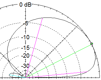
The Antiphase Pair
One special case of the passive phased pair is the antiphase
pair.
If you take two vertically-polarized antenna elements, and separate
them by an appropriate distance, and then feed them 180° out of
phase with each other, you get a sharp, bidirectional, endfire
pattern, similar to an elevated horizontal dipole antenna.
When I model this, I get even sharper lobes than the ARRL text
describes.
Such a pattern gives modest gain in two diretions, but very deep
nulls everywhere else. This kind of antenna could be used
to emphasize one or two DX directions, but cancel out every other
direction.
This is probably the easiest phased array to actually build
because it doesn't require delay calculations or circuits.
To get the 180° phase difference, simply feed one antenna
backwards from the other antenna. E.g., if using identical
vertical loops, simply reverse the antenna terminals of one antenna.
Otherwise, this antenna is very similar to the passive approach
described above, but without the delay line. Everything about
the two antenna elements north of the combiner is identical.
It's the spacing and the reversal of one antenna "polarity"
that does all the work.
It should even be possible to feed such an arrangement without any
buffer amplifiers, although I have not tried this.
Other Options
There are even simpler options for directional receiving antennas
besides the phased array. The
Beverage
and
rhombic
antennas are obvious examples. But there are others, including the
terminated loop.
That antenna can be made any size, and a mast-mounted preamplifier would
give enough signal for just about any HF band.
Experiment
Be ready to experiment. If you don't want to tinker with different
configurations and see how they work, then don't go the cheap route.
Get the phase controller, because that is the least effort to get to
a working antenna pair. Phased pairs are an advanced topic for
most amateurs, so be ready to learn new things.
If you aren't willing to invest some effort, this topic is not for
you — get a beam antenna or build a Beverage...
—
Copyright (C) 2023 by Matt Roberts, KK5JY.
All Rights Reserved.